Concept explainers
(a)
The velocity of the mass centre
Answer to Problem 18.28P
The velocity of the mass centre
Explanation of Solution
Given information:
The mass of the each plate is
Write the expression for moment of the inertia about the x- axis.
Here, the distance of mass centre from the circular plate is
Write the expression for moment of the inertia about the y- axis.
Write the expression for moment of the inertia about the z- axis.
Write expression for the product moment of inertia about the plane
Write expression for the product moment of inertia about the plane
Write expression for the product moment of inertia about the plane
The figure below shows the effective kinetic diagram of the system.
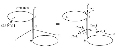
Figure-(1)
Write the expression for the impulse about point
Write the expression for the velocity of the mass centre of the system.
Here, the velocity of the mass centre in x- direction is
Calculation:
For upper plate:
Substitute
Substitute
Substitute
Substitute
For lower plate:
Substitute
Substitute
Substitute
Substitute
For assembly the inertia of the moment of both the plate is added.
Substitute
Compare coefficient of
Compare coefficient of
Compare coefficient of
Substitute
Conclusion:
The velocity of the mass centre
(b)
The angular velocity of the assembly.
Answer to Problem 18.28P
The angular velocity of the assembly is
Explanation of Solution
Write the expression for the moments about centre point
Here, the angular momentum about x- direction is
Write the expression for the angular momentum in x- direction.
Write the expression for the angular momentum in y- direction.
Write the expression for the angular momentum in z- direction.
Write the expression for the angular velocity of the assembly.
Calculation:
Substitute
Compare coefficient of
Compare coefficient of
Compare coefficient of
Substitute
Substitute
Substitute
Substitute
Substitute
Substitute
Conclusion:
The angular velocity of the assembly is
Want to see more full solutions like this?
Chapter 18 Solutions
VECTOR MECH...,DYNAMICS(LOOSE)-W/ACCESS


- Calculate the bending moment at the point D on the beam below. Take F=79 and remember that this quantity is to be used to calculate both forces and lengths. 15F 30F A сarrow_forwardShow work on how to obtain P2 and T2. If using any table, please refer to it. If applying interpolation method, please show the work.arrow_forwardcast-iron roller FIGURE P11-3 Shaft Design for Problems 11-17 Chapter 11 BEARINGS AND LUBRICATION 677 gear key P assume bearings act as simple supports 11-18 Problem 7-18 determined the half-width of the contact patch for a 1.575-in-dia steel cylinder, 9.843 in long, rolled against a flat aluminum plate with 900 lb of force to be 0.0064 in. If the cylinder rolls at 800 rpm, determine its lubrication condition with ISO VG 1000 oil at 200°F. R₁ = 64 μin (cylinder); R₁ = 32 μin (plate). 11-19 The shaft shown in Figure P11-4 was designed in Problem 10-19. For the data in the row(s) assigned from Table P11-1, and the corresponding diameter of shaft found in Problem 10-19, design suitable bearings to support the load for at least 5E8 cycles at 1200 rpm. State all assumptions. (a) (b) Using hydrodynamically lubricated bronze sleeve bearings with ON = 40, 1/ d=0.80, and a clearance ratio of 0.002 5. Using deep-groove ball bearings for a 10% failure rate. *11-20 Problem 7-20 determined the…arrow_forwardCalculate the shear force at the point D on the beam below. Take F=19 and remember that this quantity is to be used to calculate both forces and lengths. 15F A сarrow_forward"II-1 The shaft shown in Figure P11-I was designed in Problem 10-1. For the data in the row(s) assigned from Table P11-1, and the corresponding diameter of shaft found in Problem 10-1, design suitable bearings to support the load for at least 7E7 cycles at 1500 rpm. State all assumptions. (a) Using hydrodynamically lubricated bronze sleeve bearings with Ox = 20, 1/d=1.25, and a clearance ratio of 0.001 5. assume bearings act as simple supports FIGURE P11-1 Shaft Design for Problem 11-1 11-2 The shaft shown in Figure P11-2 was designed in Problem 10-2. For the data in the row(s) assigned from Table P11-1, and the corresponding diameter of shaft found in Problem 10-2, design suitable bearings to support the load for at least 3E8 cycles at 2.500 rpm. State all assumptions. (a) Using hydrodynamically lubricated bronze sleeve bearings with ON=30, 1/d=1.0, and a clearance ratio of 0.002. FIGURE P11-2 Shaft Design for Problem 11-2 Table P11-1 Data for Problems assume bearings act as simple…arrow_forwardFor the frame below, calculate the shear force at point Q. Take P=13 and note that this value is used for both the loads and the lengths of the members of the frame. 1 A Q ✗ 19 KBP 2.5P- B R C 45 degrees ✗ 1 .2P- 4PhN -P→arrow_forwardCalculate the Bending Moment at point D in the frame below. Leave your answer in Nm (newton-metres) J J A 2m 2m <2m х D 不 1m X E 5m 325 Nm 4x 400N/marrow_forwardIn the beam below, calculate the shear force at point A. Take L=78 and remember that both the loads and the dimensions are expressed in terms of L. 143 1 DX A - Li 4 LhN 14LRN/m Х B 22 3 L.arrow_forwardCalculate the Shear Force at Point F on the beam below. Keep your answer in Newtons and make shear force positive to the right. A х 2m <2m E D 5m 1m Хт 325N1m 400N/m 8arrow_forwardThe normal force at C on the beam below is equal to: A ShN C X 15h N 8 ○ OkN 2.5kN 10kN ○ 12.5kN 1m Im 1m 1m;arrow_forwardCalculate the y coordinate of the of the centroid of the shape below. Take A= 18.5 8 6A 4A X 6Aarrow_forwardIn MATLAB write out a program to integrate the equations of motion of a rigid body. The inertia matrix is given by I = [125 0 0; 0 100 0; 0 0 75] which is a diagonal, where diag operator provides a matrix with given elements placed on its diagonal. Consider three cases where the body rotates 1 rad/sec about each principal axis. Integrate the resulting motion and study the angular rates and the resulting attitude (use any attitude coordinates). For each principal axis case, assume first that a pure spin about the principal axis is performed, and then repeat the simulation where a small 0.1 rad/sec motion is present about another principal axis. Discuss the stability of each motion. The code should produce a total of 6 simulations results when it is ran.arrow_forwardarrow_back_iosSEE MORE QUESTIONSarrow_forward_iosRecommended textbooks for you
 Elements Of ElectromagneticsMechanical EngineeringISBN:9780190698614Author:Sadiku, Matthew N. O.Publisher:Oxford University Press
 Mechanics of Materials (10th Edition)Mechanical EngineeringISBN:9780134319650Author:Russell C. HibbelerPublisher:PEARSON
 Thermodynamics: An Engineering ApproachMechanical EngineeringISBN:9781259822674Author:Yunus A. Cengel Dr., Michael A. BolesPublisher:McGraw-Hill Education
 Control Systems EngineeringMechanical EngineeringISBN:9781118170519Author:Norman S. NisePublisher:WILEY
 Mechanics of Materials (MindTap Course List)Mechanical EngineeringISBN:9781337093347Author:Barry J. Goodno, James M. GerePublisher:Cengage Learning
 Engineering Mechanics: StaticsMechanical EngineeringISBN:9781118807330Author:James L. Meriam, L. G. Kraige, J. N. BoltonPublisher:WILEY
Elements Of ElectromagneticsMechanical EngineeringISBN:9780190698614Author:Sadiku, Matthew N. O.Publisher:Oxford University PressMechanics of Materials (10th Edition)Mechanical EngineeringISBN:9780134319650Author:Russell C. HibbelerPublisher:PEARSONThermodynamics: An Engineering ApproachMechanical EngineeringISBN:9781259822674Author:Yunus A. Cengel Dr., Michael A. BolesPublisher:McGraw-Hill EducationControl Systems EngineeringMechanical EngineeringISBN:9781118170519Author:Norman S. NisePublisher:WILEYMechanics of Materials (MindTap Course List)Mechanical EngineeringISBN:9781337093347Author:Barry J. Goodno, James M. GerePublisher:Cengage LearningEngineering Mechanics: StaticsMechanical EngineeringISBN:9781118807330Author:James L. Meriam, L. G. Kraige, J. N. BoltonPublisher:WILEY