
Vector Mechanics for Engineers: Statics and Dynamics
11th Edition
ISBN: 9780073398242
Author: Ferdinand P. Beer, E. Russell Johnston Jr., David Mazurek, Phillip J. Cornwell, Brian Self
Publisher: McGraw-Hill Education
expand_more
expand_more
format_list_bulleted
Concept explainers
Videos
Textbook Question
Chapter 17.2, Problem 17.77P
A sphere of radius r and mass m is projected along a rough horizontal surface with the initial velocities shown. If the final velocity of the sphere is to be zero, express (a) the required magnitude of ω0 in terms of v0 and r, (b) the time required for the sphere to come to rest in terms of v0 and the coefficient of kinetic friction μk.
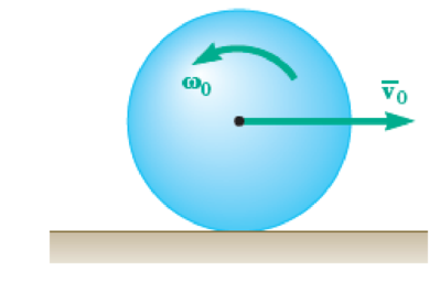
Fig. P17.77
Expert Solution & Answer

Trending nowThis is a popular solution!

Students have asked these similar questions
3. Water enters the constant 125-mm inside-diameter tubes of a boiler at 7.5 MPa and
60°C and leaves the tubes at 6 MPa and 500°C with a velocity of 75 m/s. Calculate the
velocity of the water at the tube inlet and the inlet volume flow rate.
2. A piston-cylinder device contains 2.4 kg of nitrogen initially at 120 kPa and 27°C. The
nitrogen is now compressed slowly in a polytropic process during which PV1.3 = constant
until the volume is reduced by one-half. Determine the work done and the heat transfer
for this process.
1. 1.25 m³ of saturated liquid water at 225°C is expanded isothermally in a closed system
until its quality is 75 percent. Determine the total work produced by this expansion, in kJ.
Chapter 17 Solutions
Vector Mechanics for Engineers: Statics and Dynamics
Ch. 17.1 - A round object of mass m and radius r is released...Ch. 17.1 - Prob. 17.2CQCh. 17.1 - Prob. 17.3CQCh. 17.1 - Prob. 17.4CQCh. 17.1 - Slender bar A is rigidly connected to a massless...Ch. 17.1 - A 200-kg flywheel is at rest when a constant 300...Ch. 17.1 - The rotor of an electric motor has an angular...Ch. 17.1 - Prob. 17.3PCh. 17.1 - Two disks of the same material are attached to a...Ch. 17.1 - Prob. 17.5P
Ch. 17.1 - PROBLEM 17.6
The flywheel of a punching machine...Ch. 17.1 - Prob. 17.7PCh. 17.1 - Prob. 17.8PCh. 17.1 - The 10-in.-radius brake drum is attached to a...Ch. 17.1 - Prob. 17.10PCh. 17.1 - Prob. 17.11PCh. 17.1 - Prob. 17.12PCh. 17.1 - Prob. 17.13PCh. 17.1 - The double pulley shown has a mass of 15 kg and a...Ch. 17.1 - Gear A has a mass of 1 kg and a radius of gyration...Ch. 17.1 - Prob. 17.16PCh. 17.1 - Prob. 17.17PCh. 17.1 - A slender 9-lb rod can rotate in a vertical plane...Ch. 17.1 - An adapted golf device attaches to a wheelchair to...Ch. 17.1 - Prob. 17.20PCh. 17.1 - A collar with a mass of 1 kg is rigidly attached...Ch. 17.1 - A collar with a mass of 1 kg is rigidly attached...Ch. 17.1 - Two identical slender rods AB and BC are welded...Ch. 17.1 - Prob. 17.24PCh. 17.1 - Prob. 17.25PCh. 17.1 - Prob. 17.26PCh. 17.1 - Greek engineers had the unenviable task of moving...Ch. 17.1 - A small sphere of mass m and radius r is released...Ch. 17.1 - Prob. 17.29PCh. 17.1 - A half-cylinder with mass m and radius r is...Ch. 17.1 - Prob. 17.31PCh. 17.1 - Two uniform cylinders, each of weight W = 14 lb...Ch. 17.1 - Prob. 17.33PCh. 17.1 - A bar of mass m = 5 kg is held as shown between...Ch. 17.1 - The 1.5-kg uniform slender bar AB is connected to...Ch. 17.1 - The motion of the uniform rod AB is guided by...Ch. 17.1 - Prob. 17.37PCh. 17.1 - Prob. 17.38PCh. 17.1 - The ends of a 9-lb rod AB are constrained to move...Ch. 17.1 - The mechanism shown is one of two identical...Ch. 17.1 - The mechanism shown is one of two identical...Ch. 17.1 - Each of the two rods shown is of length L = 1 m...Ch. 17.1 - The 4-kg rod AB is attached to a collar of...Ch. 17.1 - If in Prob. 17.43 the angular velocity of the...Ch. 17.1 - 17.45 The uniform rods AB and BC weigh 2.4 kg and...Ch. 17.1 - The uniform rods AB and BC weigh 2.4 kg and 4 kg,...Ch. 17.1 - The 80-mm-radius gear shown has a mass of 5 kg and...Ch. 17.1 - Prob. 17.48PCh. 17.1 - Three shafts and four gears are used to form a...Ch. 17.1 - Prob. 17.50PCh. 17.1 - Prob. 17.51PCh. 17.2 - The 350-kg flywheel of a small hoisting engine has...Ch. 17.2 - Prob. 17.2IMDCh. 17.2 - Prob. 17.3IMDCh. 17.2 - Prob. 17.52PCh. 17.2 - Prob. 17.53PCh. 17.2 - Prob. 17.54PCh. 17.2 - A uniform 144-lb cube is attached to a uniform...Ch. 17.2 - Prob. 17.56PCh. 17.2 - Prob. 17.57PCh. 17.2 - Prob. 17.58PCh. 17.2 - Prob. 17.59PCh. 17.2 - Each of the double pulleys shown has a centroidal...Ch. 17.2 - Each of the gears A and B has a mass of 675 g and...Ch. 17.2 - Prob. 17.62PCh. 17.2 - Prob. 17.63PCh. 17.2 - Prob. 17.64PCh. 17.2 - Prob. 17.65PCh. 17.2 - Show that, when a rigid body rotates about a fixed...Ch. 17.2 - Prob. 17.68PCh. 17.2 - A flywheel is rigidly attached to a 1.5-in.-radius...Ch. 17.2 - A wheel of radius r and centroidal radius of...Ch. 17.2 - Prob. 17.71PCh. 17.2 - 17.72 and 17.73 A 9-in.·radius cylinder of weight...Ch. 17.2 - 17.72 and 17.73 A 9-in.·radius cylinder of weight...Ch. 17.2 - Two uniform cylinders, each of mass m = 6 kg and...Ch. 17.2 - Prob. 17.75PCh. 17.2 - Prob. 17.76PCh. 17.2 - A sphere of radius r and mass m is projected along...Ch. 17.2 - A bowler projects an 8.5-in.-diameter ball...Ch. 17.2 - Prob. 17.79PCh. 17.2 - A satellite has a total weight (on Earth) of 250...Ch. 17.2 - Two 10-lb disks and a small motor are mounted on a...Ch. 17.2 - Prob. 17.82PCh. 17.2 - Prob. 17.83PCh. 17.2 - Prob. 17.84PCh. 17.2 - Prob. 17.85PCh. 17.2 - Prob. 17.86PCh. 17.2 - Prob. 17.87PCh. 17.2 - Prob. 17.88PCh. 17.2 - A 1.8-kg collar A and a 0.7-kg collar B can slide...Ch. 17.2 - Prob. 17.90PCh. 17.2 - A small 4-lb collar C can slide freely on a thin...Ch. 17.2 - Rod AB has a weight of 6 lb and is attached to a...Ch. 17.2 - Prob. 17.93PCh. 17.2 - Prob. 17.94PCh. 17.2 - The 6-lb steel cylinder A of radius r and the...Ch. 17.3 - A uniform slender rod AB of mass m is at rest on a...Ch. 17.3 - Prob. 17.5IMDCh. 17.3 - Prob. 17.6IMDCh. 17.3 - At what height h above its center G should a...Ch. 17.3 - A bullet weighing 0.08 lb is fired with a...Ch. 17.3 - In Prob. 17.97, determine (a) the required...Ch. 17.3 - A 16-lb wooden panel is suspended from a pin...Ch. 17.3 - Prob. 17.100PCh. 17.3 - A 45-g bullet is fired with a velocity of 400 m/s...Ch. 17.3 - A 45-g bullet is fired with a velocity of 400 m/s...Ch. 17.3 - Prob. 17.103PCh. 17.3 - Prob. 17.104PCh. 17.3 - Prob. 17.105PCh. 17.3 - A uniform slender rod AB is at rest on a...Ch. 17.3 - A bullet of mass m is fired with a horizontal...Ch. 17.3 - Determine the height h at which the bullet of...Ch. 17.3 - A uniform slender bar of length L = 200 mm and...Ch. 17.3 - A uniform slender rod of length L is dropped onto...Ch. 17.3 - A uniform slender rod AB has a mass m, a length L,...Ch. 17.3 - 17.113 The slender rod AB of length L = 1 m forms...Ch. 17.3 - The trapeze/lanyard air drop (t/LAD) launch is a...Ch. 17.3 - The uniform rectangular block shown is moving...Ch. 17.3 - The 40-kg gymnast drops from her maximum height of...Ch. 17.3 - Prob. 17.117PCh. 17.3 - Prob. 17.118PCh. 17.3 - A 1-oz bullet is fired with a horizontal velocity...Ch. 17.3 - For the beam of Prob. 17.119, determine the...Ch. 17.3 - Prob. 17.121PCh. 17.3 - Prob. 17.122PCh. 17.3 - A slender rod AB is released from rest in the...Ch. 17.3 - Prob. 17.124PCh. 17.3 - Block A has a mass m and is attached to a cord...Ch. 17.3 - Prob. 17.126PCh. 17.3 - 17.127 and 17.128Member ABC has a mass of 2.4 kg...Ch. 17.3 - 17.127 and 17.128Member ABC has a mass of 2.4 kg...Ch. 17.3 - Prob. 17.129PCh. 17.3 - Prob. 17.130PCh. 17.3 - A small rubber ball of radius r is thrown against...Ch. 17.3 - Sphere A of mass m and radius r rolls without...Ch. 17.3 - In a game of pool, ball A is rolling without...Ch. 17 - A uniform disk, initially at rest and of constant...Ch. 17 - The 8-in.-radius brake drum is attached to a...Ch. 17 - A uniform slender rod is placed at corner B and is...Ch. 17 - The motion of the slender 250-mm rod AB is guided...Ch. 17 - Prob. 17.141RPCh. 17 - Disks A and B are made of the same material, are...Ch. 17 - Disks A and B are made of the same material, are...
Additional Engineering Textbook Solutions
Find more solutions based on key concepts
A nozzle at A discharges water with an initial velocity of 36 ft/s at an angle with the horizontal. Determine ...
Vector Mechanics For Engineers
How are relationships between tables expressed in a relational database?
Modern Database Management
The following C++ program will not compile because the lines have been mixed up. cout Success\n; cout Success...
Starting Out with C++ from Control Structures to Objects (9th Edition)
17–1C A high-speed aircraft is cruising in still air. How does the temperature of air at the nose of the aircra...
Thermodynamics: An Engineering Approach
Porter’s competitive forces model: The model is used to provide a general view about the firms, the competitors...
Management Information Systems: Managing The Digital Firm (16th Edition)
Why is the study of database technology important?
Database Concepts (8th Edition)
Knowledge Booster


Learn more about
Need a deep-dive on the concept behind this application? Look no further. Learn more about this topic, mechanical-engineering and related others by exploring similar questions and additional content below.Similar questions
- An undamped single-degree-of-freedom system is subjected to dynamic excitation as shown in Figure 1.• System properties: m = 1, c = 0, k = (6π)2.• Force excitation: p(t) = posin(ωt) where po = 9 and ω = 2π.• Initial conditions: u(t = 0) = 0 and ̇u(t = 0) = 0.Please, complete Parts (a) through (d) using any computational tool of your preference. The preferred toolis MATLAB. Print and turn in a single pdf file that will include your code/calculations and your plots.(a) Generate the solution using a linear interpolation of the load over each time step (note that hereyou can use the undamped coefficients). Plot the displacement response for the first 4 seconds andcompare to the exact closed form solution. Repeat using the following time step sizes, ∆t = 0.01,0.05, 0.15, 0.20 seconds. Include the closed form solution and the solutions for different ∆t values in asingle plot. Please, provide your observations by comparing the closed form solution with the solutionsderived using the four…arrow_forwardAssume multiple single degree of freedom systems with natural periods T ∈ [0.05, 2.00] seconds with in-crement of period dT = 0.05 seconds. Assume three cases of damping ratio: Case (A) ξ = 0%; Case (B)ξ = 2%; Case (C) ξ = 5%. The systems are initially at rest. Thus, the initial conditions are u(t = 0) = 0 anḋu(t = 0) = 0. The systems are subjected to the base acceleration that was provided in the ElCentro.txt file(i.e., first column). For the systems in Case (A), Case (B), and Case (C) and for each natural period computethe peak acceleration, peak velocity, and peak displacement responses to the given base excitation. Please,use the Newmark method for β = 1/4 (average acceleration) to compute the responses. Create threeplots with three lines in each plot. The first plot will have the peak accelerations in y-axis and the naturalperiod of the system in x-axis. The second plot will have the peak velocities in y-axis and the natural periodof the system in x-axis. The third plot will have…arrow_forwardBoth portions of the rod ABC are made of an aluminum for which E = 70 GPa. Based on the given information find: 1- deformation at A 2- stress in BC 3- Total strain 4- If v (Poisson ratio is 0.25, find the lateral deformation of AB Last 3 student ID+ 300 mm=L2 724 A P=Last 2 student ID+ 300 KN 24 24 Diameter Last 2 student ID+ 15 mm Last 3 student ID+ 500 mm=L1 724 C B 24 Q=Last 2 student ID+ 100 KN 24 Diameter Last 2 student ID+ 40 mmarrow_forward
- Q2Two wooden members of uniform cross section are joined by the simple scarf splice shown. Knowing that the maximum allowable tensile stress in the glued splice is 75 psi, determine (a) the largest load P that can be safely supported, (b) the corresponding shearing stress in the splice. น Last 1 student ID+5 inch=W =9 4 L=Last 1 student ID+8 inch =12 60° P'arrow_forwardQ4 The two solid shafts are connected by gears as shown and are made of a steel for which the allowable shearing stress is 7000 psi. Knowing the diameters of the two shafts are, respectively, dBC determine the largest torque Tc that can be applied at C. 4 and dEF dBC=Last 1 student ID+3 inch dEF=Last 1 student ID+1 inch 7 R=Last 1 Student ID+5 inch 9 R B Tc 2.5 in. E TF Harrow_forwardExperiment تكنولوجيا السيارات - Internal Forced convenction Heat transfer Air Flow through Rectangular Duct. objective: Study the convection heat transfer of air flow through rectangular duct. Valve Th Top Dead Centre Exhaust Valve Class CP. N; ~ RIVavg Ti K 2.11 Te To 18.8 21.3 45.8 Nath Ne Pre Calculations:. Q = m cp (Te-Ti) m: Varg Ac Acca*b Q=hexp As (Ts-Tm) 2 2.61 18.5 20.846.3 Tm = Te-Ti = 25 AS-PL = (a+b)*2*L Nu exp= Re-Vavy D heep Dh k 2ab a+b Nu Dh the- (TS-Tm) Ts. Tmy Name / Nu exp Naxe بب ارتدان العشريarrow_forward
- Procedure:1- Cartesian system, 2D3D,type of support2- Free body diagram3 - Find the support reactions4- If you find a negativenumber then flip the force5- Find the internal force3D∑Fx=0∑Fy=0∑Fz=0∑Mx=0∑My=0\Sigma Mz=02D\Sigma Fx=0\Sigma Fy=0\Sigma Mz=05- Use method of sectionand cut the elementwhere you want to findarrow_forwardProcedure:1- Cartesian system, 2D3D,type of support2- Free body diagram3 - Find the support reactions4- If you find a negativenumber then flip the force5- Find the internal force3D∑Fx=0∑Fy=0∑Fz=0∑Mx=0∑My=0\Sigma Mz=02D\Sigma Fx=0\Sigma Fy=0\Sigma Mz=05- Use method of sectionand cut the elementwhere you want to findthe internal force andkeep either side of thearrow_forwardProcedure: 1- Cartesian system, 2D3D, type of support 2- Free body diagram 3 - Find the support reactions 4- If you find a negative number then flip the force 5- Find the internal force 3D ∑Fx=0 ∑Fy=0 ∑Fz=0 ∑Mx=0 ∑My=0 ΣMz=0 2D ΣFx=0 ΣFy=0 ΣMz=0 5- Use method of section and cut the element where you want to find the internal force and keep either side of thearrow_forward
- Procedure:1- Cartesian system, 2D3D,type of support2- Free body diagram3 - Find the support reactions4- If you find a negativenumber then flip the force5- Find the internal force3D∑Fx=0∑Fy=0∑Fz=0∑Mx=0∑My=0\Sigma Mz=02D\Sigma Fx=0\Sigma Fy=0\Sigma Mz=05- Use method of sectionand cut the elementwhere you want to findthe internal force andkeep either side of thearrow_forwardProcedure: 1- Cartesian system, 2(D)/(3)D, type of support 2- Free body diagram 3 - Find the support reactions 4- If you find a negative number then flip the force 5- Find the internal force 3D \sum Fx=0 \sum Fy=0 \sum Fz=0 \sum Mx=0 \sum My=0 \Sigma Mz=0 2D \Sigma Fx=0 \Sigma Fy=0 \Sigma Mz=0 5- Use method of section and cut the element where you want to find the internal force and keep either side of the sectionarrow_forwardProcedure: 1- Cartesian system, 2(D)/(3)D, type of support 2- Free body diagram 3 - Find the support reactions 4- If you find a negative number then flip the force 5- Find the internal force 3D \sum Fx=0 \sum Fy=0 \sum Fz=0 \sum Mx=0 \sum My=0 \Sigma Mz=0 2D \Sigma Fx=0 \Sigma Fy=0 \Sigma Mz=0 5- Use method of section and cut the element where you want to find the internal force and keep either side of the sectionarrow_forward
arrow_back_ios
SEE MORE QUESTIONS
arrow_forward_ios
Recommended textbooks for you
 Elements Of ElectromagneticsMechanical EngineeringISBN:9780190698614Author:Sadiku, Matthew N. O.Publisher:Oxford University Press
 Mechanics of Materials (10th Edition)Mechanical EngineeringISBN:9780134319650Author:Russell C. HibbelerPublisher:PEARSON
 Thermodynamics: An Engineering ApproachMechanical EngineeringISBN:9781259822674Author:Yunus A. Cengel Dr., Michael A. BolesPublisher:McGraw-Hill Education
 Control Systems EngineeringMechanical EngineeringISBN:9781118170519Author:Norman S. NisePublisher:WILEY
 Mechanics of Materials (MindTap Course List)Mechanical EngineeringISBN:9781337093347Author:Barry J. Goodno, James M. GerePublisher:Cengage Learning
 Engineering Mechanics: StaticsMechanical EngineeringISBN:9781118807330Author:James L. Meriam, L. G. Kraige, J. N. BoltonPublisher:WILEY
Elements Of Electromagnetics
Mechanical Engineering
ISBN:9780190698614
Author:Sadiku, Matthew N. O.
Publisher:Oxford University Press
Mechanics of Materials (10th Edition)
Mechanical Engineering
ISBN:9780134319650
Author:Russell C. Hibbeler
Publisher:PEARSON
Thermodynamics: An Engineering Approach
Mechanical Engineering
ISBN:9781259822674
Author:Yunus A. Cengel Dr., Michael A. Boles
Publisher:McGraw-Hill Education
Control Systems Engineering
Mechanical Engineering
ISBN:9781118170519
Author:Norman S. Nise
Publisher:WILEY
Mechanics of Materials (MindTap Course List)
Mechanical Engineering
ISBN:9781337093347
Author:Barry J. Goodno, James M. Gere
Publisher:Cengage Learning
Engineering Mechanics: Statics
Mechanical Engineering
ISBN:9781118807330
Author:James L. Meriam, L. G. Kraige, J. N. Bolton
Publisher:WILEY
Ch 2 - 2.2.2 Forced Undamped Oscillation; Author: Benjamin Drew;https://www.youtube.com/watch?v=6Tb7Rx-bCWE;License: Standard youtube license