
Concept explainers
Videos
With respect to the periodic waveform sketched in Fig. 17.30, let gn(t) represent the Fourier series representation of f(t) truncated at n. [For example, if n = 1, g1(t) has three terms, defined through a0, a1 and b1.] (a) Sketch g2(t), g3(t), and g5(t), along with f(t). (b) Calculate f (2.5), g2(2.5), g3(2.5), and g5(2.5).
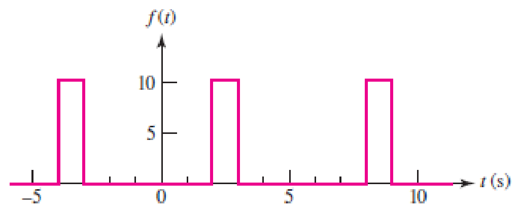
■ FIGURE 17.30
(a)
Sketch
Answer to Problem 8E
The sketch for
Explanation of Solution
Given data:
Refer to Figure 17.30 in the textbook.
Formula used:
Write the general expression for Fourier series expansion.
Write the general expression for Fourier series coefficient
Write the general expression for Fourier series coefficient
Write the general expression for Fourier series coefficient
Write the expression to calculate the fundamental angular frequency.
Here,
Calculation:
In the given Figure 17.29, the time period is
Substitute 6 for T in equation (5) to find
Substitute 6 for T in equation (2) to find the value of coefficient
Simplify the above equation as follows,
Substitute 6 for T in equation (3) to find the value of coefficient
The above equation as follows,
Substitute equation (6) in equation (7) as follows,
Now finding the Fourier coefficient
Substitute 6 for T in equation (4) to find the value of coefficient
The above equation as follows,
Substitute equation (6) in equation (9) as follows,
Substituting the value of
The function
For
Therefore, equation (11) will be as follows,
Simplify the above equation as follows,
Similarly, for
Therefore, equation (11) will be as follows,
From equation (12), the above equation is written as,
Similarly, for
Therefore, equation (11) will be as follows,
From equation (13), the above equation is written as,
MATLAB code to sketch for
t=-5:0.01:5;
g2=1.667-0.275*cos(3.141*t/3)+0.159*sin(3.141*t/3)+0.137*cos(2*3.141*t/3)-0.238*sin(2*3.141*t/3);
g3=1.667-0.275*cos(3.141*t/3)+0.159*sin(3.141*t/3)+0.137*cos(2*3.141*t/3)-0.238*sin(2*3.141*t/3)+0.212*sin(pi*t);
g5=1.667- 0.275*cos(3.141*t/3)+0.159*sin(3.141*t/3)+0.137*cos(2*3.141*t/3)-0.238*sin(2*3.141*t/3)+0.212*sin(pi*t)-0.069*cos(4*pi*t/3)-0.119*sin(4*pi*t/3)+0.055*cos(5*pi*t/3)+0.0318*sin(5*pi*t/3);
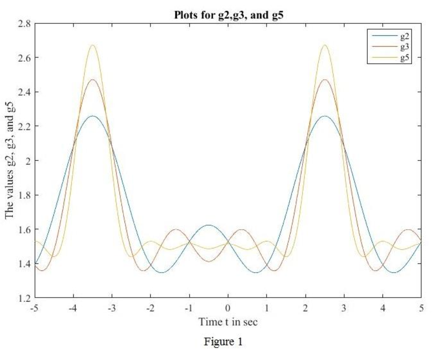
plot(t,g2,t,g3,t,g5)
legend({'g2','g3','g5'},'Location','best')
xlabel('Time t in sec')
ylabel('The values g2, g3, and g5')
title('Plots for g2,g3, and g5')
MATLAB output: The MATLAB output shown in Figure 1.
MATLAB code to sketch for
t=linspace(-5,5,1000); % vector for time over 1000 points.
T=6; % Period
w0=2*pi/T; % natural frequency, is w0=2*pi.
f0=1.667; % constant.
N=40;
for i=1:1000;
sum=0;
for n=1:N;
sum=sum+(1/n*pi)*(sin(n*pi) -sin(2*n*pi/3))*cos(n*pi*t(i)/3) + (1/n*pi)*(cos(2*n*pi/3) -cos(n*pi))*sin(n*pi*t(i)/3);
end
f40(i)=f0+sum;
end
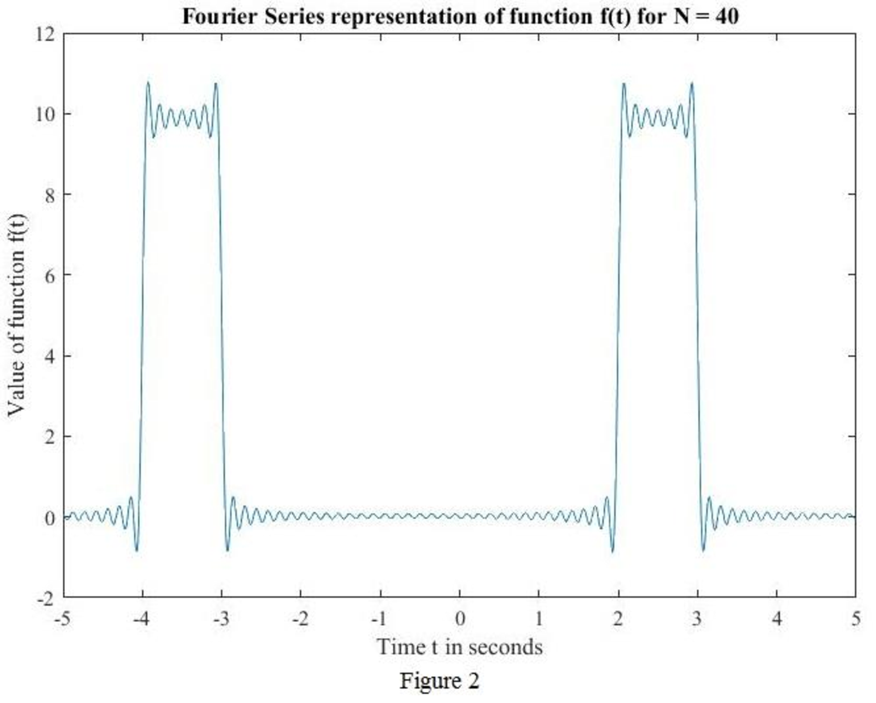
plot(t,f40)
xlabel('Time t in seconds')
ylabel('Value of function f(t)')
plot_ttle = ['Fourier Series representation of function f(t) for N = ',num2str(N)];
title(plot_ttle);
MATLAB output: The MATLAB output shown in Figure 2.
MATLAB code to sketch for
t=linspace(-5,5,1000); % vector for time over 1000 points.
T=6; % Period
w0=2*pi/T; % natural frequency, is w0=2*pi.
f0=1.667; % constant.
N=40; % consider N=40 for instant.
for i=1:1000;
g2=1.667-0.275*cos(3.141*t(i)/3)+0.159*sin(3.141*t(i)/3)+0.137*cos(2*3.141*t(i)/3)-0.238*sin(2*3.141*t(i)/3);
g3=1.667-0.275*cos(3.141*t(i)/3)+0.159*sin(3.141*t(i)/3)+0.137*cos(2*3.141*t(i)/3)-0.238*sin(2*3.141*t(i)/3)+0.212*sin(pi*t(i));
g5=1.667-0.275*cos(3.141*t(i)/3)+0.159*sin(3.141*t(i)/3)+0.137*cos(2*3.141*t(i)/3)-0.238*sin(2*3.141*t/3)+0.212*sin(pi*t)-0.069*cos(4*pi*t(i)/3)-0.119*sin(4*pi*t(i)/3)+0.055*cos(5*pi*t(i)/3)+0.0318*sin(5*pi*t(i)/3);
end
for i=1:1000;
sum=0;
for n=1:N;
sum=sum+(1/n*pi)*(sin(n*pi) -sin(2*n*pi/3))*cos(n*pi*t(i)/3) + (1/n*pi)*(cos(2*n*pi/3) -cos(n*pi))*sin(n*pi*t(i)/3);
end
f40(i)=f0+sum;
end
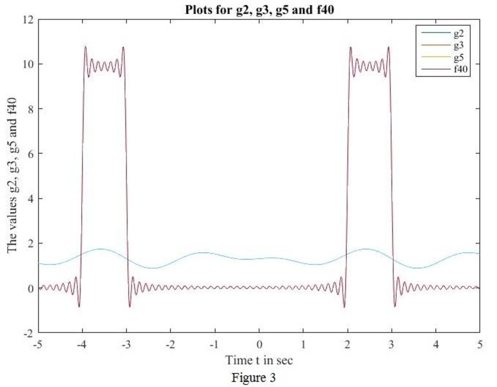
plot(t,g2,t,g3,t,g5,t,f40)
legend({'g2','g3','g5','f40'},'Location','best')
xlabel('Time t in sec')
ylabel('The values g2, g3, g5 and f40')
title('Plots for g2, g3, g5 and f40')
MATLAB output:
Conclusion:
Thus, the sketch for
(b)
Find the function
Answer to Problem 8E
The value of
Explanation of Solution
Given data:
Refer to Figure 17.30 in the textbook.
Calculation:
From Part (a), the function
Finding
From Part (a),
Finding
From Part (a),
Finding
From Part (a),
Finding
Conclusion:
Thus, the value of
Want to see more full solutions like this?
Chapter 17 Solutions
Loose Leaf for Engineering Circuit Analysis Format: Loose-leaf
Additional Engineering Textbook Solutions
BASIC BIOMECHANICS
Database Concepts (8th Edition)
Electric Circuits. (11th Edition)
Concepts Of Programming Languages
Mechanics of Materials (10th Edition)
Thermodynamics: An Engineering Approach


- Q2: Using D flip-flops, design a synchronous counter. The counter counts in the sequence 1,3,5,7, 1,7,5,3,1,3,5,7,.... when its enable input x is equal to 1; otherwise, the counter count 0.arrow_forwardFrom the collector characteristic curves and the dc load line given below, determine the following: (a) Maximum collector current for linear operation (b) Base current at the maximum collector current (c) VCE at maximum collector current. lc (mA) 600 ΜΑ 60- 500 με 50- 400 με 40- 300 μ Α 30- Q-point 200 ΜΑ 20- 10- 100 μ Α 0 VCE (V) 1 2 3 4 5 6 7 8 9 10 [6 Paarrow_forwardProcedure:- 1- Connect the cct. shown in fig.(2). a ADDS DS Fig.(2) 2-For resistive load, measure le output voltage by using oscilloscope ;then sketch this wave. 3- Measure the average values ::f VL and IL: 4- Repeat steps 2 & 3 but for RL load. Report:- 1- Calculate the D.C. output vcl age theoretically and compare it with the test value. 2- Calculate the harmonic cont :nts of the load voltage, and explain how filter components may be selected. 3- Compare between the three-phase half & full-wave uncontrolled bridge rectifier. 4- Draw the waveform for the c:t. shown in fig.(2) but after replaced Di and D3 by thyristors with a 30° and a2 = 90° 5- Draw the waveform for the cct. shown in fig.(2) but after replace the 6-diodes by 6- thyristor. 6- Discuss your results. Please solve No. 4 and 5arrow_forward
- Please I want solution by handwrittenarrow_forward8 00 ! Required information Consider the circuit given below. 0/2 points awarded 3 ΚΩ www t=0 6kM Scored R 1.5i Vc 1 μF 10 V If R = 5.00 kQ, determine vao+). The value of va(0) is 1.4545 V.arrow_forwardI want to know what does it look in a breadboard circuit, because I want to created it but I not sure it is build properly, can you give me an illustuation base on this image, it do need to real, something like virutal examplearrow_forward
- Charge neutrality Since doped semiconductor remains electroneutral, the concentration of negative charges equals the concentration of positive charges. n+ Na,ionized p+Nd,ionized np = n; 2 2 N-Na N N d d р + 2 2 n = Nd-Na 2 + Na - 2 Na +n₁ 2 71/2 1/2 2 2 +n Concentration of electrons and holes 1. Calculate concentrations of electrons and holes at room temperature in Si and Ge with donor concentration of 1.5x10¹7 cm³ and acceptor concentration of 8x1016 cm-3. 2. Will these concentrations change much with the temperature increase to 100°C?arrow_forwardAnswer the questions on the end of the image pleasearrow_forwardAnswer these two questions on the end of the image, please 1.Calculate intrinsic carrier concentration for Si, Ge and GaAs at temperatures -20°C, 20°C (room temperature) and 120°C 2.Compare the obtained data with n and p shown on previous slide 25arrow_forward
- Can you help me achieve the requirements using Arduino? I have encountered some issues with these requirements. Q.2: Suppose you have two push buttons connected to ports (0 & 1) and four LED's connected to ports (6-9). Write a program to flash ON the odd LED's if we press the switch 0 for 4s, flash ON the even LED's if we press the switch 1 for 5s and flash ON all the LED's otherwise for 6s.arrow_forwardCharge carrier concentration in doped semiconductor: compensation n = Na - Na Na - Na >> ni n-type p = n₁²/n 2 if N₂ >> N₁, n = N₁_ and _p=n² / Na d p = Na-Nd p-type Na-Na >> n₁ d 2 n = n₁₂²/p 2 if N₁ >> N₁, p = N₁ and n = n² / Na a n-type Dopant compensation: Examples d n = Na-N₁ = 4×10¹ cm¯ -3 ++++++ n = 4×1016 cm-³ N=6×1016 cm-3 p=n/n=1020/4×1016 = 2.5×10³ cm p-type -3 p=Na-N₁ =8×10 −6×1016 = 2×10¹6 cm³ n=n²/p=1020/2×101 =5×10³ cm³ N2×1016 cm³ ++++++ N=6x1016 cm-3 N = 8×1016 cm-3 p=2×1016 cm³ The resulting charge carrier concentration in compensated semiconductor approximately equals the difference between the donor and acceptor concentrations. Charge carrier concentration in n-type and p-type semiconductors 1. Calculate concentrations of electrons and holes at room temperature in Si containing 2x1017 cm³ of donors and 8x10¹⁶ -3 cm³ of acceptors. Assume that Na, Nd >> n;. αν 2. Calculate concentrations of electrons and holes at room temperature in Ge containing 2x10¹7 cm³ of…arrow_forwardlonization energy of dopants in semiconductors lonization energy of shallow donors and acceptors can be evaluated using hydrogenic model: lonization energy E Hion and orbital radius a, of hydrogen atom Hydrogen Atom moe4 EHion = 13.6 eV a = 8ε²h² Απερη mee² = 5.2918 x 10⁻¹¹ m lonization energy Eion and orbital radius D,A of donors and acceptors electron m* e4 Eion = ~50 meV 8K² &²h² 4πεερη2 "D,A 1 nm m*e² Orbit of an electron bound to a donor in a semiconductor crystal. Energy levels of donors and acceptors Conduction Band ↓ Ec -Ed Donor Level Donor ionization energy Acceptor ionization energy Acceptor Level Εα Ev Valence Band Ionization energy of selected donors and acceptors in silicon Donors Acceptors Dopant Sb P As B Al In Ionization energy, Ec-Ed or Ea-E, (meV) 39 44 54 45 57 160 Hydrogenic model of donors and acceptors Calculate the ionization energies and orbit radii of donors and acceptors in Si and Ge. Dielectric constant of silicon is k = 11.7. Dielectric constant of…arrow_forward
 Introductory Circuit Analysis (13th Edition)Electrical EngineeringISBN:9780133923605Author:Robert L. BoylestadPublisher:PEARSON
 Delmar's Standard Textbook Of ElectricityElectrical EngineeringISBN:9781337900348Author:Stephen L. HermanPublisher:Cengage Learning
 Programmable Logic ControllersElectrical EngineeringISBN:9780073373843Author:Frank D. PetruzellaPublisher:McGraw-Hill Education
 Fundamentals of Electric CircuitsElectrical EngineeringISBN:9780078028229Author:Charles K Alexander, Matthew SadikuPublisher:McGraw-Hill Education
 Electric Circuits. (11th Edition)Electrical EngineeringISBN:9780134746968Author:James W. Nilsson, Susan RiedelPublisher:PEARSON
 Engineering ElectromagneticsElectrical EngineeringISBN:9780078028151Author:Hayt, William H. (william Hart), Jr, BUCK, John A.Publisher:Mcgraw-hill Education,