
Concept explainers
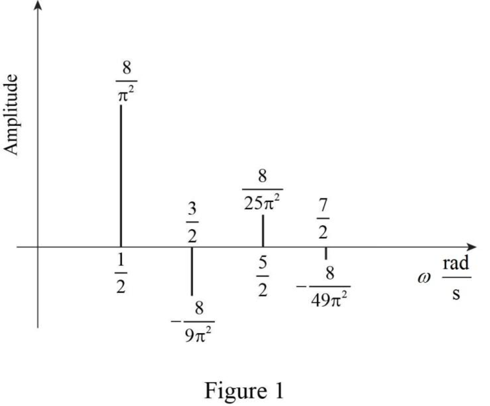
Sketch the line spectrum for the waveform shown in Figure 17.4c (limited to the five largest terms).
Answer to Problem 14E
The line spectrum for the waveform shown in Figure 17.4c is sketched as shown in Figure 1.
Explanation of Solution
Given data:
Refer to Figure 17.4c in the textbook.
Formula used:
Write the general expression for Fourier series expansion.
Write the general expression for Fourier series coefficient
Write the general expression for Fourier series coefficient
Write the general expression for Fourier series coefficient
Write the expression to calculate the fundamental angular frequency.
Here,
Calculation:
In the given Figure 17.4a, the time period is
The function
Substitute 2 for T in equation (5) to find
Applying equation (6) in equation (2) to find
Simplify the above equation as follows,
As the given function is an odd symmetry. Therefore,
Applying equation (6) in equation (4) to finding the Fourier coefficient
Equation (8) is simplified as,
Therefore, equation (8) becomes,
Consider the function,
Consider the following integration formula.
Compare the equations (10) and (11) to simplify the equation (10).
Using the equation (11), the equation (10) can be reduced as,
Simplify the above equation as follows,
Consider the function,
Compare the equations (12) and (11) to simplify the equation (12).
Using the equation (11), the equation (12) can be reduced as,
Simplify the above equation as follows,
Substituting the values of x and y in equation (9) as follows,
Converting the equation (1) which is in angular frequency into frequency.
Substitute the values of
For
For
The sketch for the line spectrum of
Conclusion:
Thus, the line spectrum for the waveform shown in Figure 17.4c is sketched as shown in Figure 1.
Want to see more full solutions like this?
Chapter 17 Solutions
Loose Leaf for Engineering Circuit Analysis Format: Loose-leaf


- 3. Describe the function of the lowpass filter (LPF) used in CVSD system.arrow_forwardDon't use ai to answer I will report you answerarrow_forwardRL +Vcc a VCE 2. a) For the direct coupled class A amplifier shown, derive the expression for efficiency in terms of maximum and minimum values of currents and voltages. b) Determine the maximum efficiency of this circuit. c) Derive the expression for maximum power dissipation. www 9 www RB in VBEarrow_forward
- The joint probability density function of two discrete random variables X and Y is given by p(x, y)=c(2x+y), where x and y can assume all integers such that 0≤ x≤2, 0≤ y ≤ 3, and p (x, y)= 0 otherwise. a) Find the value of the constant c. (c) Find P(X≥1, Y≤2). (b) Find P(X=2, Y= 1).arrow_forwardA wattmeter is connected with the positive lead on phase "a" of a three-phase system. The negative lead is connected to phase "b". A separate wattmeter has the positive lead connected to phase "c". The negative lead of this wattmeter is connected also to phase "b". If the input voltage is 208 volts line-to- line, the phase sequence is "abc" and the load is 1200 ohm resistors connected in "Y", what is the expected reading of each of the wattmeters? (Hint: draw a phasor diagram)arrow_forward1- Write the mesh equation for the circuit below. Solve the equations using Crame method (matrix and determinant), and find the current of resistor 4 ohm. 6 A www 10 Ω w 6Ω www 12 V + 402 www 12 Ω 2- Write the nodal equations for the circuit below. You do not need to solve the equation just write the matrix equation. R3 ww 8Ω R₁ 201 5 A 12 3A R₂40arrow_forward
- Please solve these 3 questions in detailarrow_forward1. Please draw the root locus by hand for the following closed-loop system, where G(s) s+8 S-2 and H(s) = Find the range of K for stability Input R(s) Output C(s) KG(s) H(s) s+6 = S-2arrow_forwardThe state-space Jordan Canonical Form of the following system is: Y(s) 8-5 U(s) (+1)(+3) Select one: O a. -1 0 0 A = 0 -1 0 B: ... ... ... 0 0 C [4 1.5 1.5], D=0 b. -3 1 0 0 A = 0 -3 0 1 B ... 0 0 -1 C -4 -1.5 1.5], D=0 ○ C. -3 1 0 A = 0 -3 0 1 ,B= ... 0 0 ○ d. C [4 1.5 1.5], D=0 -3 1 0 0 A = 0 -3 0 1 , B: ... ... 0 0 -1 C [4 1.5 1.5], D=0 -4 1 If= x and (0): = then 2(t) is: -4 0 Select one: a. x2(t)=4te2t O b. x2(t) = e2t+2te2t Oc. 2(t)=-4te-21 Od. 2(t) e2-2te-2 =arrow_forward
 Introductory Circuit Analysis (13th Edition)Electrical EngineeringISBN:9780133923605Author:Robert L. BoylestadPublisher:PEARSON
 Delmar's Standard Textbook Of ElectricityElectrical EngineeringISBN:9781337900348Author:Stephen L. HermanPublisher:Cengage Learning
 Programmable Logic ControllersElectrical EngineeringISBN:9780073373843Author:Frank D. PetruzellaPublisher:McGraw-Hill Education
 Fundamentals of Electric CircuitsElectrical EngineeringISBN:9780078028229Author:Charles K Alexander, Matthew SadikuPublisher:McGraw-Hill Education
 Electric Circuits. (11th Edition)Electrical EngineeringISBN:9780134746968Author:James W. Nilsson, Susan RiedelPublisher:PEARSON
 Engineering ElectromagneticsElectrical EngineeringISBN:9780078028151Author:Hayt, William H. (william Hart), Jr, BUCK, John A.Publisher:Mcgraw-hill Education,