
Concept explainers
(a)
The value of output voltage,
(a)
Answer to Problem 61E
The value of output voltage,
Explanation of Solution
Given data:
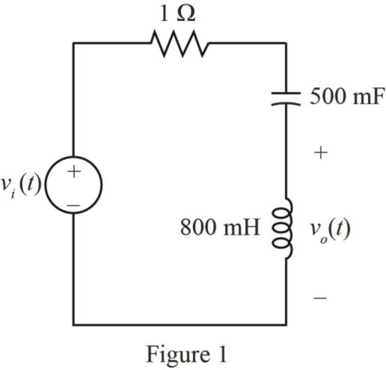
The input voltage is,
The given diagram is shown in Figure 1.
Calculation:
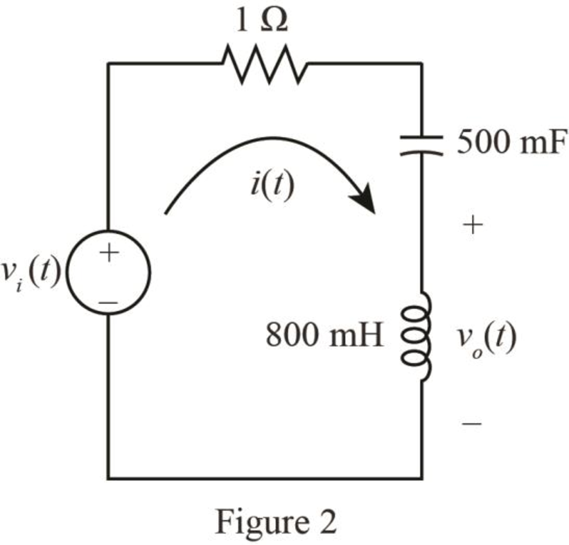
Mark the loop current
The required diagram is shown in Figure 2.
The conversion of
The conversion of
Hence, the value of the inductor,
The conversion of
The conversion of
Hence, the value of the capacitor,
The expression for output voltage using KVL is given by,
Substitute
Apply Fourier transform to the above expression.
The Fourier transform of
Substitute
Further solve as,
Apply shifting property for
Further solve as,
The inverse Fourier transform for the
The inverse Fourier transform for the
The inverse Fourier transform for the
Substitute
The expression for the output voltage from the figure is given by,
Substitute
Further solve as,
Conclusion:
Therefore, the value of output voltage,
(b)
The value of output voltage,
(b)
Answer to Problem 61E
The value of output voltage,
Explanation of Solution
Given data:
The input voltage is,
Calculation:
The expression for output voltage using KVL is given by,
Substitute
Apply Fourier transform to the above expression.
The Fourier transform of
Substitute
Further solve as,
The inverse Fourier transform for the
The inverse Fourier transform for the
Substitute
The expression for the output voltage from the figure is given by,
Substitute
Further solve as,
Conclusion:
Therefore, the value of output voltage,
Want to see more full solutions like this?
Chapter 17 Solutions
Loose Leaf for Engineering Circuit Analysis Format: Loose-leaf


- 12.2 Evaluate each of the following integrals. (a) G₁: = = √ (31³ +21² + 1) [8(t) +48 (t − 2)] dt -21 (b) G₂ = G2 = 4(e¯2ª +1)[☎(t) −28(t − 2)] dt -2 -20 (c) G3 = 0 3( cos 2π- 1) [8(t) +☎(t − 10)] dt -20arrow_forward3) The differential amplifier in Figure 3 is biased with a three-transistor current source. The transistor parameters are ẞ= 100, VBE (on) = 0.7 V, and VA = ∞. a) Determine I1. Ic2, IC4, VCE2, and VCE4. b) Determine a new value of R1 such that VCE4 = 2.5V. what are the values of Ic4, Ic2, I1, and R₁? +5 V Q1 R₁ = 8.5 ΚΩ IC4 23 RC= • 2 ΚΩ + 24 VCE4 RC= 2 ΚΩ est Ic2 + Q2 VCE2 -5 V Figure 3arrow_forward12.1 Evaluate each of the following integrals: (a) G₁ = √(33-4t²+3)[8(t) +28(t − 2)] dt. (b) G₂ = √442(e³ +1)[8(t) − 28(t − 2)] dt. .16 -31 (c) G3=124t sin(2лt) − 1][§(t − 1) +☎(t − 6)] dt.arrow_forward
- Why is the voltage drop of a self-excited generator greater than the voltagedrop of a separately excited generator?arrow_forwardWhen driving a DC shunt generator with a synchronous prime mover motor, why does the AC amperage to the synchronous motor machine increase as load is added to the generator?arrow_forward100 What is the phase and gain margins of the following system, is it stable or not. Design a PI controller for the following unstable process if any. 50 -120 -130 0 -140 -50 -150 -100 -160 <<-150 -170 -200 -180 10-1 10° 10¹ 102 103 104 105 1071 10° 10¹ 102 103 101 105 Frequency (rad/s) Frequency (rad/s)arrow_forward
- Please assist in the below questionarrow_forwardA. For the RL-circuit with i(0)=0, Find the current i(t) using LT R=2 Ω V(t)=sin3t B. Find Invers Laplace Transform for Z(s) L= 1H 4s2 +2s+3 = s2-3s+2arrow_forwardGiven the circuit diagram in. Find the following voltages: Vda, Vbh, Vgc, Vdi, Vfa, Vac, Vai, Vhf, Vfb, and Vdc.arrow_forward
- L ✓ 30 UF 2mtt The voltage applied across 3-branched circuit of figure 2 is given by v = 100 sin(5000t+ π/4). Calculate the branch currents and total current. v 25ŹR 00arrow_forward10 mA 2 ΚΩ 2 ΚΩ 6 ΚΩ x + ww 4 ΚΩ 4 ΚΩ +1 2 Varrow_forwardFind Vx,V1,V3,V0 according to the case of the circuits using KVLarrow_forward
 Introductory Circuit Analysis (13th Edition)Electrical EngineeringISBN:9780133923605Author:Robert L. BoylestadPublisher:PEARSON
 Delmar's Standard Textbook Of ElectricityElectrical EngineeringISBN:9781337900348Author:Stephen L. HermanPublisher:Cengage Learning
 Programmable Logic ControllersElectrical EngineeringISBN:9780073373843Author:Frank D. PetruzellaPublisher:McGraw-Hill Education
 Fundamentals of Electric CircuitsElectrical EngineeringISBN:9780078028229Author:Charles K Alexander, Matthew SadikuPublisher:McGraw-Hill Education
 Electric Circuits. (11th Edition)Electrical EngineeringISBN:9780134746968Author:James W. Nilsson, Susan RiedelPublisher:PEARSON
 Engineering ElectromagneticsElectrical EngineeringISBN:9780078028151Author:Hayt, William H. (william Hart), Jr, BUCK, John A.Publisher:Mcgraw-hill Education,