Concept explainers
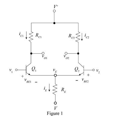
Consider the differential amplifier circuit in Figure 17.1 biased at
(a)
The design parameters of the circuit for the given values.
Answer to Problem 17.1EP
The value of the resistances to design the circuit are for
Explanation of Solution
Calculation:
The given circuit is shown in Figure 1.

The expression for the voltage at the emitter terminals is given by,
Substitute
The expression to determine the value of the current
Substitute
The expression to determine the value of the collector current of the first transistor is given by,
Substitute
The expression for the value of the collector current of the second transistor is given by,
Substitute
The expression for the value of the voltage
Substitute
Conclusion:
Therefore, the value of the resistances to design the circuit are for
(b)
The value of the current
Answer to Problem 17.1EP
The value of the current and the voltage for the value of the input voltage of
Explanation of Solution
Calculation:
The expression for the voltage at the emitter terminals is given by,
Substitute
The expression to determine the value of the current
Substitute
The expression to determine the value of the collector current of the first transistor is given by,
Substitute
The expression for the value of the collector current of the second transistor is given by,
The expression for the value of the voltage
Substitute
The expression for the value of the voltage
Substitute
The expression for the voltage at the emitter terminals is given by,
Substitute
The expression to determine the value of the current
Substitute
The expression to determine the value of the collector current of the first transistor is given by,
The expression for the value of the collector current of the second transistor is given by,
Substitute
The expression for the value of the voltage
Substitute
The expression for the value of the voltage
Substitute
Conclusion:
Therefore, the value of the current and the voltage for the value of the input voltage of
(c)
The value of the power dissipated in the circuit for the different value of the input voltage.
Answer to Problem 17.1EP
The value of the power consumed in the circuit for the input voltage of
Explanation of Solution
Calculation:
The expression for the value of the power dissipated in the circuit.
Substitute
Substitute
Conclusion:
Therefore, the value of the power consumed in the circuit for the input voltage of
Want to see more full solutions like this?
Chapter 17 Solutions
MICROELECT. CIRCUIT ANALYSIS&DESIGN (LL)
- No chatgpt pls will upvote Already got wrong chatgpt answerarrow_forward"I need an expert solution with detailed steps for integration." The normalized Far-field pattern of an antenna is given by: E = √√sine (cosq) Determine: 1) Beam solid angle 2) Exact Directivity 0≤0≤ 180, while 0≤≤180, and 270 ≤≤ 360 3) HPBW in both azimuth and elevationarrow_forward"I need an expert solution with detailed steps for integration." Find Directivity, the effect aperture and aperture efficiency of the antenna, if it has physical aperture of 2.4 x 10⁻²-2 and the radiation intensity can be approximated by: U(0, 4) = (sesce 0°s0<20° 20°ses600 1.0°≤≤ 360°arrow_forward
- Don't use ai to answer I will report you answerarrow_forwardDon't use ai to answer I will report you answerarrow_forward"Can you explain the integration method to show the result?" The radiation intensity of an aperture antenna, mounted on an infinite ground plane with perpendicular to the aperture, is rotationally symmetric (not a function of 4), and it is given by U = π sin Find the approximate directivity (dimensionless and in dB) using (a) numerical integration. Use the DIRECTIVITY computer program at the end of this chapter. U sin ( sin ) sin (a) Directly Do = 14.0707 = 10log (14.0707) = 11.48 dBarrow_forward
- Don't use ai to answer I will report you answerarrow_forwardcomplete the table in the attached photos. instructions are below the tablearrow_forwardPlease show the solution and answers in each. Thank you. A 120 MVA, 19.5 kV generator has Xₛ = 1.5 pu and is connected to a transmission line by a transformer rated 150 MVA , 230 wye/18 delta kV Watts, and X = 0.1 pu. If the base to be used in the calculation is 100 MVA, 230 kV for the transmission line. a. Find the per-unit values to be used for the transformer and generator reactances. b. If the transformer delivers 80% of its rated capacity to the line at 220 kV, express the current in per unit. c. Find also the current in the genrator in amperes.arrow_forward
- I need an expert mathematical solution. The radiation intensity of an aperture antenna, mounted on an infinite ground plane with perpendicular to the aperture. is rotationally symmetric (not a function of 4), and it is given by U sin (77 sin 0) π sin Find the approximate directivity (dimensionless and in dB) using numerical integration. Use the DIRECTIVITY computer program at the end of this chapter.arrow_forwardDon't use ai to answer I will report you answer.arrow_forwardDon't use ai to answer I will report you answerarrow_forward
 Introductory Circuit Analysis (13th Edition)Electrical EngineeringISBN:9780133923605Author:Robert L. BoylestadPublisher:PEARSON
 Delmar's Standard Textbook Of ElectricityElectrical EngineeringISBN:9781337900348Author:Stephen L. HermanPublisher:Cengage Learning
 Programmable Logic ControllersElectrical EngineeringISBN:9780073373843Author:Frank D. PetruzellaPublisher:McGraw-Hill Education
 Fundamentals of Electric CircuitsElectrical EngineeringISBN:9780078028229Author:Charles K Alexander, Matthew SadikuPublisher:McGraw-Hill Education
 Electric Circuits. (11th Edition)Electrical EngineeringISBN:9780134746968Author:James W. Nilsson, Susan RiedelPublisher:PEARSON
 Engineering ElectromagneticsElectrical EngineeringISBN:9780078028151Author:Hayt, William H. (william Hart), Jr, BUCK, John A.Publisher:Mcgraw-hill Education,


