
Concept explainers
Videos
The test rig shown was developed to perform fatigue testing on fitness trampolines. A motor drives the 200-mm radius flywheel AB, which is pinned at its center point A, in a counterclockwise direction with a constant angular velocity of 120 rpm. The flywheel is attached to slider CD by the 400-mm connecting rod BC. The mass of the connecting rod BC is 5 kg, and the mass of the link CD and foot is 2 kg. At the instant when θ = 0° and the foot is just above the trampoline, determine the force exerted by pin C on rod BC.
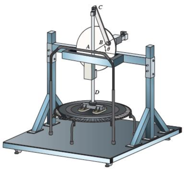
Fig. P16.127
Find the force exerted by pin C on rod BC for fitness trampoline.
Answer to Problem 16.127P
The force exerted by pin C on rod BC is
Explanation of Solution
Given information:
The radius of the flywheel AB is
The mass of the connecting rod BC is
The mass of the link CD and foot is
The length of the rod BC is
The angular velocity is
The angle is
Calculation:
Convert the unit of angular velocity from
Consider the acceleration due to gravity as
Calculate the weight
Calculate the weight of rod BC
Substitute
Calculate the weight of link CD
Substitute
Sketch the geometry of the rig as shown in Figure 1.
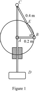
Refer to Figure 1.
Calculate the angle
Calculate the position vectors
Position of B with respect to A.
Position of C with respect to B.
Position of G with respect to B.
Calculate the moment of inertia
Substitute
Sketch the Free Body Diagram of the rod CD as shown in Figure 2.
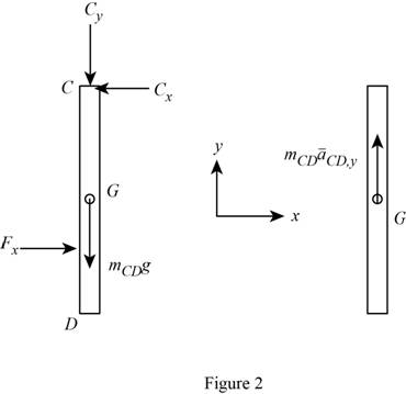
Refer to Figure 2.
Apply the Equilibrium of forces along y direction as shown below.
Substitute
Sketch the Free Body Diagram of rod BC as shown in Figure 3.
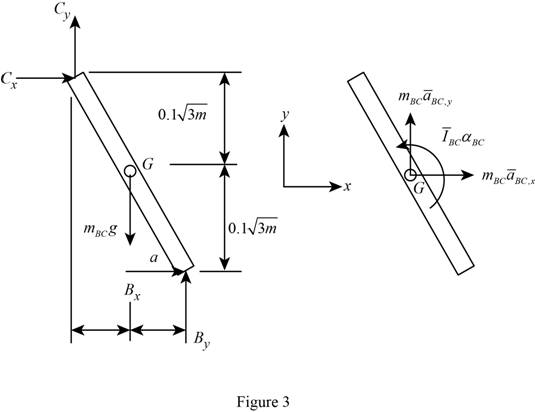
Refer to Figure 3.
Apply the Equilibrium of forces along x direction as shown below.
Substitute
Apply the Equilibrium of forces along y direction as shown below.
Substitute
Apply the Equilibrium of moment about G as shown below.
Substitute
Calculate the velocity
Substitute
Calculate the velocity
Substitute
Resolving the i and j components as shown below.
For i component.
For j component.
Substitute
Calculate the relative acceleration
Substitute
Calculate the relative acceleration
Substitute
Resolving i and j components as shown below.
For i component,
For j component,
Substitute
Calculate the relative acceleration
Substitute
Resolving i and j components as shown below.
Calculate the reaction
Substitute
Calculate the reaction
Substitute
Calculate the reaction
Substitute
Substitute
Calculate the reaction at C as shown below.
Substitute
Therefore, the force exerted by pin C on rod BC is
Want to see more full solutions like this?
Chapter 16 Solutions
VECTOR MECH...,STAT.+DYN.(LL)-W/ACCESS
Additional Engineering Textbook Solutions
Vector Mechanics For Engineers
Mechanics of Materials (10th Edition)
SURVEY OF OPERATING SYSTEMS
Database Concepts (8th Edition)
Thermodynamics: An Engineering Approach
Modern Database Management


- Qu. 5 Composite materials are becoming more widely used in aircraft industry due to their high strength, low weight and excellent corrosion resistant properties. As an engineer who is given task to design the I beam section of an aircraft (see Figure 7) please, answer the following questions given the material properties in Table 3. Determine the Moduli of Elasticity of Carbon/Epoxy, Aramid/Epoxy, and Boron /Epoxy composites in the longitudinal direction, given that the composites consist of 25 vol% epoxy and 75 vol% fiber. What are the specific moduli of each of these composites? What are the specific strengths (i.e. specific UTS) of each of these composites? What is the final cost of each of these composites?please show all work step by step problems make sure to see formula material sciencearrow_forwardMueh Battery operated train Coll 160,000kg 0.0005 0.15 5m² 1.2kg/m³ CD Af Pair 19 пре neng 0.98 0.9 0.88 Tesla Prated Tesla Trated "wheel ng Joxle 270 kW 440NM 0,45m 20 8.5kg m2 the middle Consider a drive cycle of a 500km trip with 3 stops in Other than the acceleration and deceleration associated with the three stops, the tran maintains constat cruise speed velocity of 324 km/hr. The tran will fast charge at each stop for 15 min at a rate Peharge = 350 kW ΟΙ 15MIN Stop w charging (350kW) (ผม τ (AN GMIJ t 6M 1) HOW MUCH DISTANCE dace is covered DURING THE ACCELERATION TO 324 km/hr? 2) DETERMINE HOW LONG (IN seconds) the tran will BE TRAVELING AT FULL SPEED 2 ? 3) CALCULATE THE NET ENERGY GAW PER STOP etearrow_forwardPlease stop screenshoting ai solution,it always in accurate solve normalarrow_forward
- Research and select any different values for the Ratio of connecting rod length to crank radius from various engine models, then analyze how these changes affect instantaneous velocity and acceleration, presenting your findings visually using graphs.arrow_forwardPb 9) 4.44 bas gnibus& WX 002 grillimatul fred bail (e) For the simply supported I-beam, a load of 1000 lb in center. Find the maximum transverse shear stress. Compare your answer with the approximation obtained by dividing the shear load by the area of the web only with the web considered to extend for the full 8-in depth. - 3½ in. 12 bas in 0% to tolerabib tormi no grived in. 8 in. 38 in. 12 ½ in.arrow_forwardPb 12) 4.61 Draw the Mohr circle for the stresses experienced by the surface of an internally pressurized steel tube that is subject to the tangential and axial stresses in the outer surface of 45 ksi and 30 ksi, respectively, and a torsional stress of 18 ksi. yx 18 45 30arrow_forward
- Pb 8) 4.39 For the C-clamp shown, what force F can be exerted by the screw if the maximum tensile stress in the clamp is to be limited to 30 ksi? F 2 in. სის 3436 16 13 blos 0101 alos12 nodus 121A (s 3 in. in. 16 in. 16 web leonas OFF elson yollA (d 016 (& d of bolow-bloo ai 15912 020112LA sue) vilisub 22 bal.90 Swman a bris ctxibasqqA) laste is tools?arrow_forwardQuiz/An eccentrically loaded bracket is welded to the support as shown in Figure below. The load is static. The weld size for weld w1 is h1 = 6mm, for w2 h2 = 5mm, and for w3 is h3 =5.5 mm. Determine the safety factor (S.f) for the welds. F=22 kN. Use an AWS Electrode type (E90xx). 140 S Find the centroid I want university professor solutions O REDMI NOTE 8 PRO CAI QUAD CAMERA 101.15 Farrow_forwardPb 6) 4.31 do = 25 mm 4.31 What bending moment is required to produce a maximum normal stress of 400 MPa: (a) In a straight round rod of 40-mm diameter? (b) In a straight square rod, 40 mm on a side (with bending about the X axis as shown for a rectangular section in Appendix B-2)?arrow_forward
- Pb 13) 4.73 Find the maximum value of stress at the hole and semicircular notch. 45000 N 50 mm 100 mm 15 mm 25 mm 45000 Narrow_forwardPb 11) 4.53 Consider the 1-in solid round shaft supported by self-aligning bearings at A and B. Attached to the shaft are two chain sprockets that are loaded as shown. Treat this as a static loading problem and identify the specific shat location subjected to the most severe state of stress and make a Mohr circle representation of this stress state. 1-in.-dia. shaft 500 lb 2 in. 1000 lb 3 in. 3 in.arrow_forwardPb 5) 4.19 Estimate the torque required to produce a maximum shear stress of 570 MPa in a hollow shaft having an inner diameter of 20 mm and an outer diameter of 25 mm. d; = 20 mm T d = 25 mm Tmax = 570 MPaarrow_forward
 Elements Of ElectromagneticsMechanical EngineeringISBN:9780190698614Author:Sadiku, Matthew N. O.Publisher:Oxford University Press
 Mechanics of Materials (10th Edition)Mechanical EngineeringISBN:9780134319650Author:Russell C. HibbelerPublisher:PEARSON
 Thermodynamics: An Engineering ApproachMechanical EngineeringISBN:9781259822674Author:Yunus A. Cengel Dr., Michael A. BolesPublisher:McGraw-Hill Education
 Control Systems EngineeringMechanical EngineeringISBN:9781118170519Author:Norman S. NisePublisher:WILEY
 Mechanics of Materials (MindTap Course List)Mechanical EngineeringISBN:9781337093347Author:Barry J. Goodno, James M. GerePublisher:Cengage Learning
 Engineering Mechanics: StaticsMechanical EngineeringISBN:9781118807330Author:James L. Meriam, L. G. Kraige, J. N. BoltonPublisher:WILEY