
Concept explainers
Videos
The 6-kg rod BC connects a 10-kg disk centered at A to a 5-kg rod CD. The motion of the system is controlled by the couple M applied to disk A. Knowing that at the instant shown disk A has an angular velocity of 36 rad/s clockwise and no angular acceleration, determine (a) the couple M, (b) the components of the force exerted at C on rod BC.
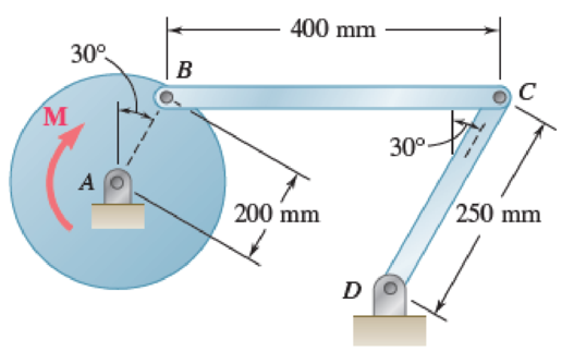
Fig. P16.135 and P16.136
(a)
Find the couple M.
Answer to Problem 16.135P
The couple M is
Explanation of Solution
Given information:
The mass of the rod BC is
The mass of the disk is
The mass of the rod CD is
The angular velocity is
The angular acceleration is
Calculation:
Consider the acceleration due to gravity as
Calculate the velocity of disk AB
Substitute
Calculate the velocity of rod BC
The velocity of disk AB is equal to the velocity of rod BC.
Substitute
Calculate the angular velocity of rod CD
Substitute
Apply the acceleration analysis as shown below.
Calculate the acceleration for disk AB
Substitute
Calculate the acceleration for rod BC
Substitute
Calculate the acceleration for rod CD
Substitute
Equating the components of Equations (1) and (2) as shown below.
Along x component.
Along y component.
Substitute
Calculate the acceleration of the mass centers as shown below.
Calculate the acceleration of mass center for disk AB
Calculate the acceleration of the mass center at P for rod BC
Substitute
Substitute
Calculate the acceleration of the mass center at Q for rod CD
Substitute
Calculate the inertial terms at mass centers as shown below.
The inertia terms at centers are
For disk AB.
For rod BC.
Substitute
For rod CD.
Substitute
Calculate the mass moment of inertia
For disk AB.
Substitute
For rod BC.
Substitute
For rod CD.
Substitute
Calculate the effective couples at mass centers as shown below.
The inertia terms at centers are
For disk AB.
For rod BC.
Substitute
For rod CD.
Substitute
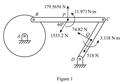
Sketch the effective force and couples on the system as shown in Figure 1.
Sketch the Free Body Diagram of the rod BC as shown in Figure 2.
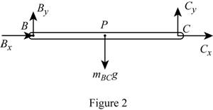
Refer to Figure 2.
Apply the Equilibrium of moment about B as shown below.
Substitute
Sketch the Free Body Diagram of the rod CD as shown in Figure 3.
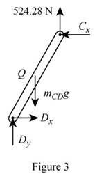
Refer to Figure 3.
Apply the Equilibrium of moment about D as shown below.
Substitute
Sketch the Free Body Diagram of the rod AB and BC as shown in Figure 4.
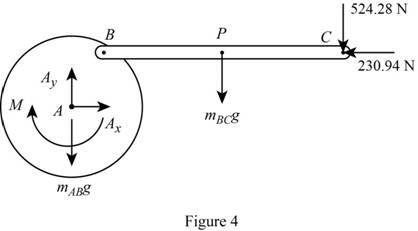
Refer to Figure 4.
Apply the Equilibrium of moment about A as shown below.
Substitute
Therefore, the couple M is
(b)
The components of force exerted at C on rod BC.
Answer to Problem 16.135P
The components of force exerted at C on rod BC is
Explanation of Solution
Given information:
The mass of the rod BC is
The mass of the disk is
The mass of the rod CD is
The angular velocity is
The angular acceleration is
Calculation:
Refer to part (a).
The components of force exerted at C on rod BC along x direction is
The components of force exerted at C on rod BC along y direction is
Therefore, the components of force exerted at C on rod BC is
Want to see more full solutions like this?
Chapter 16 Solutions
VECTOR MECH...,STAT.+DYN.(LL)-W/ACCESS
Additional Engineering Textbook Solutions
Fluid Mechanics: Fundamentals and Applications
Electric Circuits. (11th Edition)
Experiencing MIS
Starting Out With Visual Basic (8th Edition)
Elementary Surveying: An Introduction To Geomatics (15th Edition)
Thermodynamics: An Engineering Approach


- Table of Measurements and Results: Reading m/s Ji- a (wh Nu h Re Nu Error% (C) (°C) 2 1 Discussion: 1-Estimate the heat transfer and experimental value of the heat transfer coefficient hex with its unit and Nusselt number Nu expl 2- Find the percentage error for the value of the experimental Nusselt number. 3-Draw the graph showing a relationship between the temperatures difference (T-T) and theoretical and experimental value of Nusselt number. 4-The forced convection heat transfer coefficient of a plate depends on which of the following: a-gravity. b-velocity of fluid. e-conductivity of fluid. d-conductivity of plate material. Experiment: Internal Forced convenction Heat trovate on now through t objectives. Study the convection heat transfer of air flow through stage Calculations. Q & (T-T) Vary Re Q. heup A (TT) (T. Te-T ASPL Nep Re 117 RITT 14 ' 14arrow_forwardIf AE = 1.6 m, ED = CD = 1.9 m and F = 3.1 kN, then find the magnitude of the force acting in EB. B 30° 30° C E D ED m DC m ♥F KNarrow_forwardAssume multiple single degree of freedom systems with natural periods T ∈ [0.05, 2.00] seconds with in- crement of period dT = 0.05 seconds. Assume three cases of damping ratio: Case (A) ξ = 0%; Case (B) ξ = 2%; Case (C) ξ = 5%. The systems are initially at rest. Thus, the initial conditions are u(t = 0) = 0 and ̇u(t = 0) = 0. The systems are subjected to the base acceleration that was provided in the ElCentro.txt file (i.e., first column). For the systems in Case (A), Case (B), and Case (C) and for each natural period compute the peak acceleration, peak velocity, and peak displacement responses to the given base excitation. Please, use the Newmark method for β = 1/4 (average acceleration) to compute the responses. Create three plots with three lines in each plot. The first plot will have the peak accelerations in y-axis and the natural period of the system in x-axis. The second plot will have the peak velocities in y-axis and the natural period of the system in x-axis. The third plot…arrow_forward
- Determine the resultant stress at points P and Q.arrow_forwardFor the notched specimen with h = 0.13 m and r =11 mm, calculate the nominal stress for F=5 kN. F h F 25 mm Please submit your answer in the units of MPa.arrow_forwardA tensile specimen made of hot-rolled AISI 1020 steel is loaded to point corresponding to a strain of 49%. 60 Su = 66 ksi Stress σ (ksi) Sy = 39 ksi 400B Se = 36 ksi Hot-rolled 1020 steel 20 F 0 0 10 20 30 40 50 60 70 80 90 100 110 120 130 140 150 160 Strain € (%) 0 1.1 1.2 1.3 1.4 1.5 1.6 1.7 1.8 1.9 2.0 2.1 2.2 2.3 2.4 2.5 2.6 Area ratio R 0.1 0.2 0.3 0.4 0.5 Area reduction A, What value of Su is applicable to this location? 0.6arrow_forward
- A tensile specimen made of hot-rolled AISI 1020 steel is loaded to point corresponding to a strain of 40%. 60 Su = 66 ksi Stress σ (ksi) 40 20 Sy= = 39 ksi Se = 36 ksi Hot-rolled 1020 steel F | G | H 0 10 20 30 40 50 60 0 70 80 90 100 110 120 130 140 150 160 Strain € (%) ☐ T 1.1 1.2 1.3 1.4 1.5 1.6 1.7 1.8 1.9 2.0 2.1 2.2 2.3 2.4 2.5 2.6 Area ratio R 0.1 0.2 0.3 0.4 0.5 Area reduction A, What value of Sy is applicable to this location? 0.6arrow_forwardA vertical .2m by .2m square plate is exposed to saturated water vapor at atmospheric pressure. If the surface temperature is 80 degrees C and the flow is laminar, estimate the loal heat transfer coefficents at the middles and at the bottom of the plate.arrow_forwardA transformer that is 10 cm long, 6.2 cm wide, and 5 cm high is to be cooled by attaching a 10 cm by 6.2 cm wide polished aluminum heat sink(emissivity=.03) to its top surface. The heat sink has seven fins, which are 5 mm high, 2mm thick, and 10 cm long. A fan blows air at 25 degrees C parallel to the passages between the fins. The heat sink is to dissipate 12W of heat, and the base temp of the ehat sink is not to exceed 60 degrees C. Assuming the fins and the base plate to be nearly isothermal and the radiation heat transfer to be negligible, determine the minimum free-stream velocity the fan needs to supply to avoid overheating. Assume the flow is laminar over the entire finned surface of the transformer.arrow_forward
- I need a mechanical engineering expert to solve this question,no Ai pleasearrow_forwardCan you give me the meaning of Combination spanner and Give Examples of Spannersarrow_forwardHW8 A shaft fitted with a flywheel rotates at 650 r.p.m. and drives a machine. The torque of machine varies in a cyclic manner over a period of 2 revolutions. The torque rises from 650 N-m to 2200 N-m uniformly during 110° and remains constant for the following 270°. It then falls uniformly to 600 N-m during the next 100° and remains constant for the end cycle, the cycle being repeated thereafter. Determine the power required to drive the machine and percentage fluctuation in speed, if the driving torque applied to the shaft is constant and the mass of the flywheel is 180 kg with radius of gyration of 35 cm. HW9arrow_forward
 Elements Of ElectromagneticsMechanical EngineeringISBN:9780190698614Author:Sadiku, Matthew N. O.Publisher:Oxford University Press
 Mechanics of Materials (10th Edition)Mechanical EngineeringISBN:9780134319650Author:Russell C. HibbelerPublisher:PEARSON
 Thermodynamics: An Engineering ApproachMechanical EngineeringISBN:9781259822674Author:Yunus A. Cengel Dr., Michael A. BolesPublisher:McGraw-Hill Education
 Control Systems EngineeringMechanical EngineeringISBN:9781118170519Author:Norman S. NisePublisher:WILEY
 Mechanics of Materials (MindTap Course List)Mechanical EngineeringISBN:9781337093347Author:Barry J. Goodno, James M. GerePublisher:Cengage Learning
 Engineering Mechanics: StaticsMechanical EngineeringISBN:9781118807330Author:James L. Meriam, L. G. Kraige, J. N. BoltonPublisher:WILEY