
Concept explainers
Videos
(a)
Find whether the slipping occurs between the belt and either cylinder.
(a)
Explanation of Solution
The force pulled between cylinders A and B (P) is
The weight of the cylinder A
The weight of the cylinder B
The coefficient of the static friction
The coefficient of the kinetic friction
The radius of the cylinder A
The radius of the cylinder B
Calculation:
Consider the acceleration due to gravity (g) as
Convert the unit of the radius of the cylinder A
Convert the unit of the radius of the cylinder B
Consider that no slipping occurs.
Calculate the acceleration of the belt
Calculate the mass of the cylinder A
Substitute
Calculate the mass of the cylinder B
Substitute
Calculate the mass moment of inertia of the cylinder A
Substitute
Calculate the mass moment of inertia of the cylinder B
Substitute
Show the free body diagram of the cylinder A as in Figure 1.
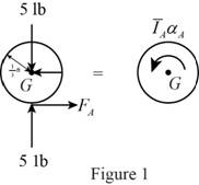
Here,
Refer to Figure 1.
Calculate the moment about point G by applying the equation of equilibrium:
Substitute
Show the free body diagram of the cylinder B as in Figure 2.
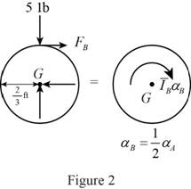
Here,
Refer to Figure 2.
Calculate the moment about point G by applying the equation of equilibrium:
Substitute
Show the free body diagram of the belt as in Figure 3.
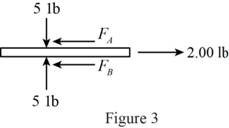
Refer to Figure 3.
Calculate the horizontal forces by applying the equation of equilibrium:
Sum of horizontal forces is equal to 0.
Calculate the angular acceleration of the cylinder A
Substitute
Calculate the horizontal force of the cylinder A
Substitute
Calculate the horizontal force of the cylinder B
Substitute
Calculate the magnitude of the friction force
Substitute
The horizontal forces of the cylinder A and B are greater than the magnitude of the friction force
Therefore, there is no slipping occurs between cylinders and belt.
(b)
Find the angular acceleration of each cylinder
(b)
Answer to Problem 16.40P
The angular acceleration of each cylinder
Explanation of Solution
The force pulled between cylinders A and B (P) is
The weight of the cylinder A
The weight of the cylinder B
The coefficient of the static friction
The coefficient of the kinetic friction
The radius of the cylinder A
The radius of the cylinder B
Calculation:
Refer the part (a).
Consider the no slipping occur at cylinder B.
Therefore, the angular acceleration of the cylinder B is
Calculate the angular acceleration of the cylinder A
Substitute
Calculate the angular acceleration of the cylinder B
Substitute
Hence, the angular acceleration of each cylinder
Want to see more full solutions like this?
Chapter 16 Solutions
VECTOR MECH. FOR EGR: STATS & DYNAM (LL


- What is the moment of Inertia of this body? What is Ixx, Iyy, and Izzarrow_forwardConsider a glass window (Hight = 1.2 m, Width = 2 m). The room thatfaces the window are maintained at 25 o C. The average temperature ofthe inner surface of the window is 5 o C. Calculate the total heat transferrate from through the window a) IdenCfy what type(s) of convecCon is important (circle one). • external forced (Chapter 7)• internal forced (Chapter 8)• natural convecCon (Chapter 9)• boiling and condensaCon (Chapter 10)b) IdenCfy the necessary equaCon(s) needed to solve the problem. c) IdenCfy important fluid properCes you need to solve the problem. d) Calculate the total heat transferred.arrow_forwardWater is condensing on a square plate (0.5 m x 0.5 m) placed verCcally. If the desired rate ofcondensaCon is 0.016 kJ/s, determine the necessary surface temperature of the plate at atmosphericpressure. Assume the film temperature of 90 o C for evaluaCon of fluid properCes of water and thesurface temperature of 80 o C for the evaluaCon of modified latent heat of vaporizaConarrow_forward
- Water at 20 o C enters the 4 cm-diameter, 14 m-long tube at a rate of 0.8 kg/s. The surfacetemperature of the pipe is maintained at 165 o Cby condensing geothermal stream at the shellside of the heat exchanger. Use water properCesat 85 o C for all calculaCons.(a) Show that the water flow is turbulent and thermally fully developed. (b) EsCmate the heat transfer coefficient for convecCve heat transfer from the pipe to the water. For a fully developed turbulent flow within the smooth pipe, the Nu number can becalculated from the following equaCon:(c) Calculate the exit temperature of the water. (d) Share your opinion on whether the use of water properties at 85°C is appropriate. Yes or No because:arrow_forwardConsider a hot automotive engine, which can beapproximated as a 0.5-m-high, 0.40-m-wide, and 0.8-m-long rectangular block. The bottom surface of the block isat a temperature of 100°C and has an emissivity of 0.95.The ambient air is at 20°C, and the road surface is at25°C. Determine the rate of heat transfer from the bottomsurface of the engine block by convection and radiationas the car travels at a velocity of 80 km/h. Assume theflow to be turbulent over the entire surface because of theconstant agitation of the engine block. a) Calculate convective heat transfer coefficient (h). b) Calculate the total heat transfer ratearrow_forward8 mm- Top view -200 mm-180 mm- D B B 12 mm Side view B -8 mm D PROBLEM 1.56 In an alternative design for the structure of Prob. 1.55, a pin of 10-mm-diameter is to be used at A. Assuming that all other specifications remain unchanged, determine the allowable load P if an overall factor of safety of 3.0 is desired. PROBLEM 1.55 In the structure shown, an 8- mm-diameter pin is used at A, and 12-mm- diameter pins are used at B and D. Knowing that the ultimate shearing stress is 100 MPa at all connections and that the ultimate normal stress is 250 MPa in each of the two links joining B and D, determine the allowable load P if an overall factor of safety of 3.0 is desired. 20 mm P 8 mm- 12 mm- Front viewarrow_forward
- Where on the beam below is the Maximum Deflection likely to occur? 2P A "ती Point A Point B Point C Point D Point B or Point D ८ B पarrow_forwardSign in ||! PDE 321 proje X IMB321 PDF Lecture 5 X PDF Planet Ec X PDF Planet Ec X PDF PEABWX PDF meeting x PDF GSS Quo X PDF File C:/Users/KHULEKANI/Downloads/CIVE%20281%20Ass-2.pdf Draw | | All | a | Ask Copilot + 1 of 7 | D SOLUTION B PROBLEM 12.16 Block 4 has a mass of 40 kg, and block B has a mass of 8 kg. The coefficients of friction between all surfaces of contact are μ, = 0.20 H = 0.15. Knowing that P = 50 N→, determine (a) the acceleration of block B, (b) the tension in the cord. Constraint of cable: 2x + (x-x1) = x + x = constant. a+ag = 0, or aB = -a Assume that block A moves down and block B moves up. Block B: +/ΣF, = 0: NAB - WB cos 0 = 0 =ma: -T+μN + Wsin = We as g + ΣΕ We Eliminate NAB and aB- NAB B Nas HN UNA A NA -T+W(sin+μcоsе) = WB- g VD"M- g Block A: +/ΣF, = 0: NA-NAB - W₁cos + Psinė = 0 N₁ = N AB+W cose - Psin = (WB+WA)cose - Psinė ΣF=ma -T+Wsino-FAB-F + Pcos = CIVE 281 X + Ждал g Q | го || حالم ☑arrow_forwardWhere on the below beam is the Maxiumum Slope likely to occur? 120 Point A Point B Point C Point B or Point C B сarrow_forward
- A very thin metallic sheet is placed between two wood plates of different thicknesses. Theplates are firmly pressed together and electricity is passed through the sheet. The exposed surfaces ofthe two plates lose heat to the ambient fluid by convection. Assume uniform heating at the interface.Neglect end effects and assume steady state.[a] Will the heat transfer through the two plates be the same? Explain.[b] Will the exposed surfaces be at the same temperature? Explainarrow_forwardDesign consideration requires that the surface of a small electronic package be maintained at atemperature not to exceed 82 o C. Noise constraints rule out the use of fans. The power dissipated inthe package is 35 watts and the surface area is 520 cm2 . The ambient temperature and surroundingwalls are assumed to be at 24 o C. The heat transfer coefficient is estimated to be 9.2 W/m2- oC andsurface emissivity is 0.7. Will the package dissipate the required power without violating designconstraints?arrow_forwardConsider radiation from a small surface at 100 oC which is enclosed by a much larger surface at24 o C. Determine the percent increase in the radiation heat transfer if the temperature of the smallsurface is doubled.arrow_forward
 International Edition---engineering Mechanics: St...Mechanical EngineeringISBN:9781305501607Author:Andrew Pytel And Jaan KiusalaasPublisher:CENGAGE L