
Loose Leaf for Engineering Circuit Analysis Format: Loose-leaf
9th Edition
ISBN: 9781259989452
Author: Hayt
Publisher: Mcgraw Hill Publishers
expand_more
expand_more
format_list_bulleted
Concept explainers
Videos
Textbook Question
Chapter 16, Problem 5E
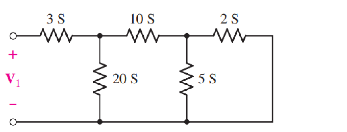
For the one-port network represented schematically in Fig. 16.35, choose the bottom node as the reference; name the junction between the 3, 10, and 20 S conductances V2 and the remaining node V3. (a) Write the three nodal equations. (b) Compute ∆Y. (c) Calculate the input admittance.
Expert Solution & Answer
Want to see the full answer?
Check out a sample textbook solution
Students have asked these similar questions
Calculate the magnitude of the current in the coils e1, e2 of the magnetic circuit, if:
ɸa = 3,00 x 10⁻³ Wb, φb = 0,80 x 10⁻³ Wb, ɸc = 2,20 x 10⁻³ Wb
L AB = 0,10 m, L AFEB = L ACDB = 0,40 m
AAB = 5,0 cm2 A AFEB = A ACDB = 20 cm2
Material characteristics
H (At/m) 240 350 530 1300 5000 9000
B (T) 0,7 0,9 1,1 1,3 1,5 1,6
Power systems
Explain the advantages and disadvantages of using silicon (Si) anode versus graphitic anode (C6) and write charging reactions for these anodes.
Explain the effect of increasing state of charge window (SOC) of lithium battery and how SOC-window impact energy density and cycle life of the battery.
Chapter 16 Solutions
Loose Leaf for Engineering Circuit Analysis Format: Loose-leaf
Ch. 16.1 - Find the input impedance of the network shown in...Ch. 16.1 - Write a set of nodal equations for the circuit of...Ch. 16.2 - By applying the appropriate 1 V sources and short...Ch. 16.2 - Prob. 4PCh. 16.2 - Prob. 5PCh. 16.3 - Prob. 6PCh. 16.3 - Use Y and Y transformations to determine Rin for...Ch. 16.4 - Find z for the two-port shown in (a) Fig. 16.23a;...Ch. 16.4 - Prob. 9PCh. 16.5 - Prob. 10P
Ch. 16.5 - Prob. 11PCh. 16.6 - Prob. 12PCh. 16 - For the following system of equations, (a) write...Ch. 16 - With regard to the passive network depicted in...Ch. 16 - Determine the input impedance of the network shown...Ch. 16 - For the one-port network represented schematically...Ch. 16 - Prob. 6ECh. 16 - Prob. 7ECh. 16 - Prob. 8ECh. 16 - Prob. 9ECh. 16 - (a) If both the op amps shown in the circuit of...Ch. 16 - Prob. 11ECh. 16 - Prob. 12ECh. 16 - Prob. 13ECh. 16 - Prob. 14ECh. 16 - Prob. 15ECh. 16 - Prob. 16ECh. 16 - Prob. 17ECh. 16 - Prob. 18ECh. 16 - Prob. 19ECh. 16 - Prob. 20ECh. 16 - For the two-port displayed in Fig. 16.49, (a)...Ch. 16 - Prob. 22ECh. 16 - Determine the input impedance Zin of the one-port...Ch. 16 - Determine the input impedance Zin of the one-port...Ch. 16 - Employ Y conversion techniques as appropriate to...Ch. 16 - Prob. 26ECh. 16 - Prob. 27ECh. 16 - Prob. 28ECh. 16 - Compute the three parameter values necessary to...Ch. 16 - It is possible to construct an alternative...Ch. 16 - Prob. 31ECh. 16 - Prob. 32ECh. 16 - Prob. 33ECh. 16 - Prob. 34ECh. 16 - The two-port networks of Fig. 16.50 are connected...Ch. 16 - Prob. 36ECh. 16 - Prob. 37ECh. 16 - Obtain both the impedance and admittance...Ch. 16 - Prob. 39ECh. 16 - Determine the h parameters which describe the...Ch. 16 - Prob. 41ECh. 16 - Prob. 42ECh. 16 - Prob. 43ECh. 16 - Prob. 44ECh. 16 - Prob. 45ECh. 16 - Prob. 46ECh. 16 - Prob. 47ECh. 16 - Prob. 48ECh. 16 - Prob. 49ECh. 16 - Prob. 50ECh. 16 - (a) Employ suitably written mesh equations to...Ch. 16 - Prob. 52ECh. 16 - Prob. 53ECh. 16 - The two-port of Fig. 16.65 can be viewed as three...Ch. 16 - Consider the two separate two-ports of Fig. 16.61....Ch. 16 - Prob. 56ECh. 16 - Prob. 57ECh. 16 - Prob. 58ECh. 16 - (a) Obtain y, z, h, and t parameters for the...Ch. 16 - Four networks, each identical to the one depicted...Ch. 16 - A cascaded 12-element network is formed using four...Ch. 16 - Prob. 62ECh. 16 - Continuing from Exercise 62, the behavior of a ray...
Additional Engineering Textbook Solutions
Find more solutions based on key concepts
Consider the adage Never ask a question for which you do not want the answer. a. Is following that adage ethica...
Experiencing MIS
1.2 Explain the difference between geodetic and plane
surveys,
Elementary Surveying: An Introduction To Geomatics (15th Edition)
How does a computers main memory differ from its auxiliary memory?
Java: An Introduction to Problem Solving and Programming (8th Edition)
The solid steel shaft AC has a diameter of 25 mm and is supported by smooth bearings at D and E. It is coupled ...
Mechanics of Materials (10th Edition)
Look at the following description of a problem domain:
Starting Out with Java: From Control Structures through Data Structures (4th Edition) (What's New in Computer Science)
How is the hydrodynamic entry length defined for flow in a pipe? Is the entry length longer in laminar or turbu...
Fluid Mechanics: Fundamentals and Applications
Knowledge Booster


Learn more about
Need a deep-dive on the concept behind this application? Look no further. Learn more about this topic, electrical-engineering and related others by exploring similar questions and additional content below.Similar questions
- Don't use guidelines okk just solve all accurate only 100% sure experts solve it correct complete solutions okkkarrow_forward3. Consider the circuit, in which R₁ = 10 KQ2, R2 = 5 KQ, R3 = 1 KQ, and RE = 8 KQ. The supply voltages are +Vcc = 10 V and -VEE = -5 V. Other parameters are ẞF = 100, VBE(On) = 0.7 V, and VCE(Sat) 0.2 V. Rc value will be specified later. (a) (3 points) Draw the dc equivalent circuit of the circuit. VI +Vcc Rc R2 RI R₁ RE -VEE υο R3 (b) Find the Thevenin equivalent voltage source VEQ and input resistance REQ of the DC equivalent circuit. Show your work. +Vcc Rc UC VEQ www REQ VE VEQ = REQ = ΚΩ RE VEEarrow_forward5. Consider the ac equivalent circuit of an amplifier, where RE = 1 KS2, gm = 0.05 S, and Υπ= 2Κ Ω. (a) Redraw the ac equivalent circuit using the hybrid-pi small signal model for BJTS. Include ro in the model. R₁ ww Vi RB ww + RL Vo RE (b) Find the terminal resistance RIB using the circuit obtained in (a). Ignore ro. Show your work. (Don't use formula for RiB.)arrow_forward
- 4. Consider the circuit. Use the symbol || to indicate the parallel of resistors in the following questions. (a) Express the input resistance Rin in terms of the terminal resistance and other necessary resistor values. (In other words, RiB, Ric, and RIE are given.) C₁ R₁ R₂ +Vcc Rc C3 R3 C2 ی RE -VEE (b) Express the output resistance Rout in terms of the terminal resistance and other necessary resistor values. (In other words, RiB, Ric and RiE are given.) (c) Express the voltage gain A₁ = ∞ in terms of terminal voltage gain Avt, the terminal Vi resistance, and other necessary resistor values. (Avt, RiB, Ric and R₁E are given.) +51arrow_forward2. ẞ 100, VBE(on)= 0.7 V, and VCE(sat) = 0.2 V for the BJT. We want to find the Q-point through the following steps. Show your work. a) Find the bias voltage VTH Using Thevenin's equivalent circuit. R1|| R2 www +5 V R₁ = 20 k IB VTH Answer: VTH = V b) Find the base current voltage IB. www. Answer: IB = μA (note the unit.) c) Find the collector voltage Vc (with reference to the ground). RC= 2.3 k B E R₂ = 30 k -5 V www R₁ = 5 ΚΩ ww AHI› RE= 5 ΚΩarrow_forward3. Consider the circuit, in which R₁ = 10 KQ2, R2 = 5 KQ, R3 = 1 KQ, and RE = 8 KQ. The supply voltages are +Vcc = 10 V and -VEE = -5 V. Other parameters are ẞF = 100, VBE(On) = 0.7 V, and VCE(Sat) 0.2 V. Rc value will be specified later. (a) (3 points) Draw the dc equivalent circuit of the circuit. VI +Vcc Rc R2 RI R₁ RE -VEE υο R3 (b) Find the Thevenin equivalent voltage source VEQ and input resistance REQ of the DC equivalent circuit. Show your work. +Vcc Rc UC VEQ www REQ VE VEQ = REQ = ΚΩ RE VEEarrow_forward
- The solution is with a pen and paper. Really not smartarrow_forward1. Consider the following mechanical system. Obtain the differential equation model for the system. Write the transfer function of the system also. Note here, input u(t) is force and output x(t) is the displacement of the mass. x (Output) k1 k2 www u(t) m (Input force) No frictionarrow_forwardNO AI PLEASEarrow_forward
arrow_back_ios
SEE MORE QUESTIONS
arrow_forward_ios
Recommended textbooks for you
 Power System Analysis and Design (MindTap Course ...Electrical EngineeringISBN:9781305632134Author:J. Duncan Glover, Thomas Overbye, Mulukutla S. SarmaPublisher:Cengage Learning
Power System Analysis and Design (MindTap Course ...
Electrical Engineering
ISBN:9781305632134
Author:J. Duncan Glover, Thomas Overbye, Mulukutla S. Sarma
Publisher:Cengage Learning
Z Parameters - Impedance Parameters; Author: Electrical Engineering Authority;https://www.youtube.com/watch?v=qoD4AoNmySA;License: Standard Youtube License