
Videos
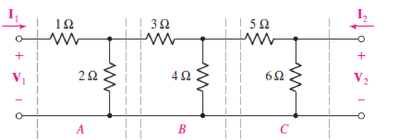
The two-port of Fig. 16.65 can be viewed as three separate cascaded two-ports A, B, and C. (a) Compute t for each network. (b) Obtain t for the cascaded network. (c) Verify your answer by naming the two middle nodes Vx and Vy, respectively, writing nodal equations, obtaining the admittance parameters from your nodal equations, and converting to t parameters using Table 16.1.
(a)
The
Answer to Problem 54E
The
Explanation of Solution
Calculation:
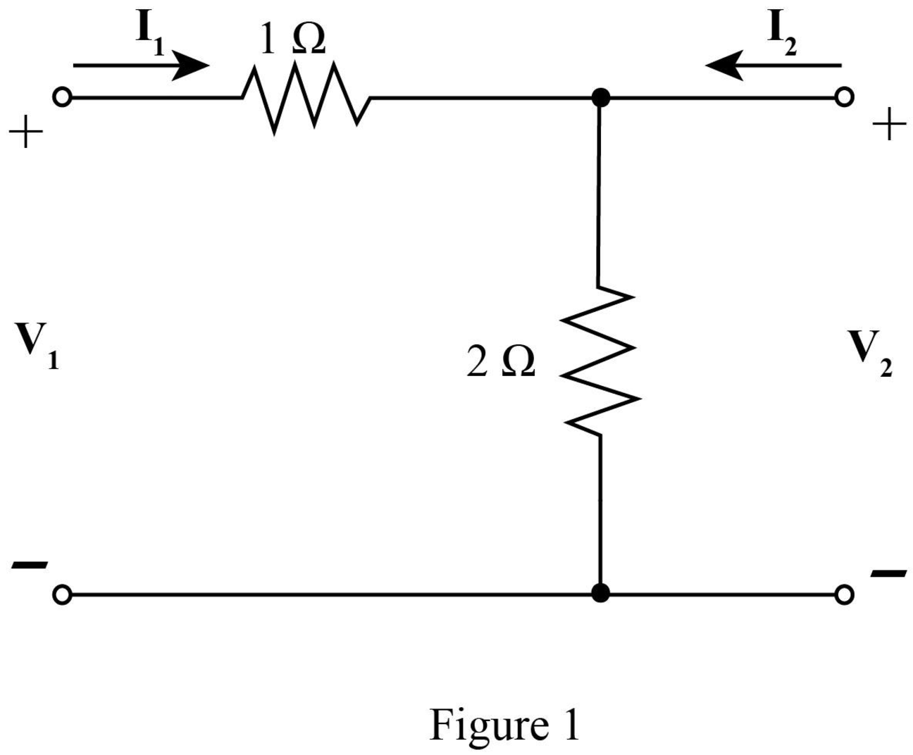
The required diagram is shown in Figure 1.
Here,
The mesh equation from the input side is given by,
The mesh equations at the output side is given by,
Substitute
The
Here,
Write equations (6) and (7) in matrix form.
Compare equation (3) with equation (4).
Compare equation (2) with equation (6).
The
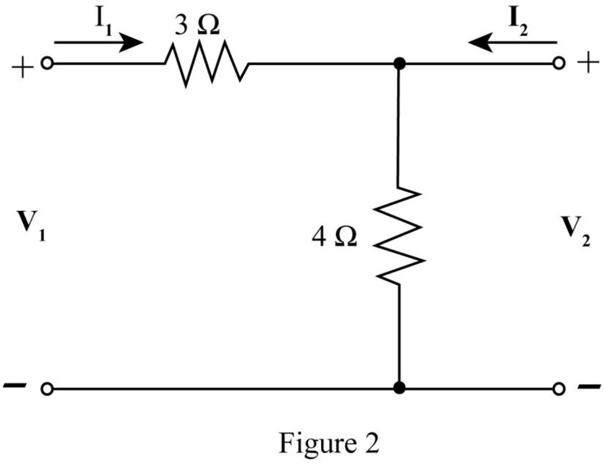
The required diagram is shown in Figure 2.
The mesh equation from the input side is given by,
The mesh equations at the output side is given by,
Substitute
Compare equation (8) with equation (4).
Compare equation (7) with equation (5).
The
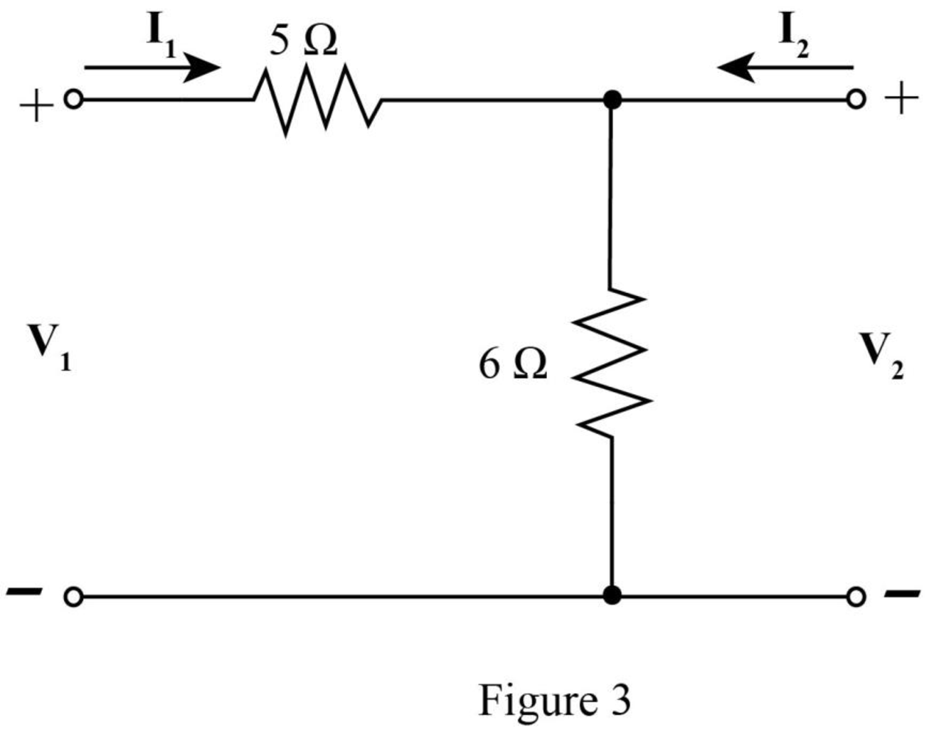
The required diagram is shown in Figure 3.
The mesh equation from the input side is given by,
The mesh equations at the output side is given by,
Substitute
Compare equation (11) with equation (4).
Compare equation (10) with equation (5).
The
Conclusion:
Therefore, the
(b)
The
Answer to Problem 54E
The
Explanation of Solution
Calculation:
The
Substitute
Conclusion:
Therefore, the
(c)
To verify: The above answers by obtaining the admittance parameter and converting them to
Answer to Problem 54E
The values have been verified.
Explanation of Solution
Calculation:
The required diagram is shown in Figure 4.
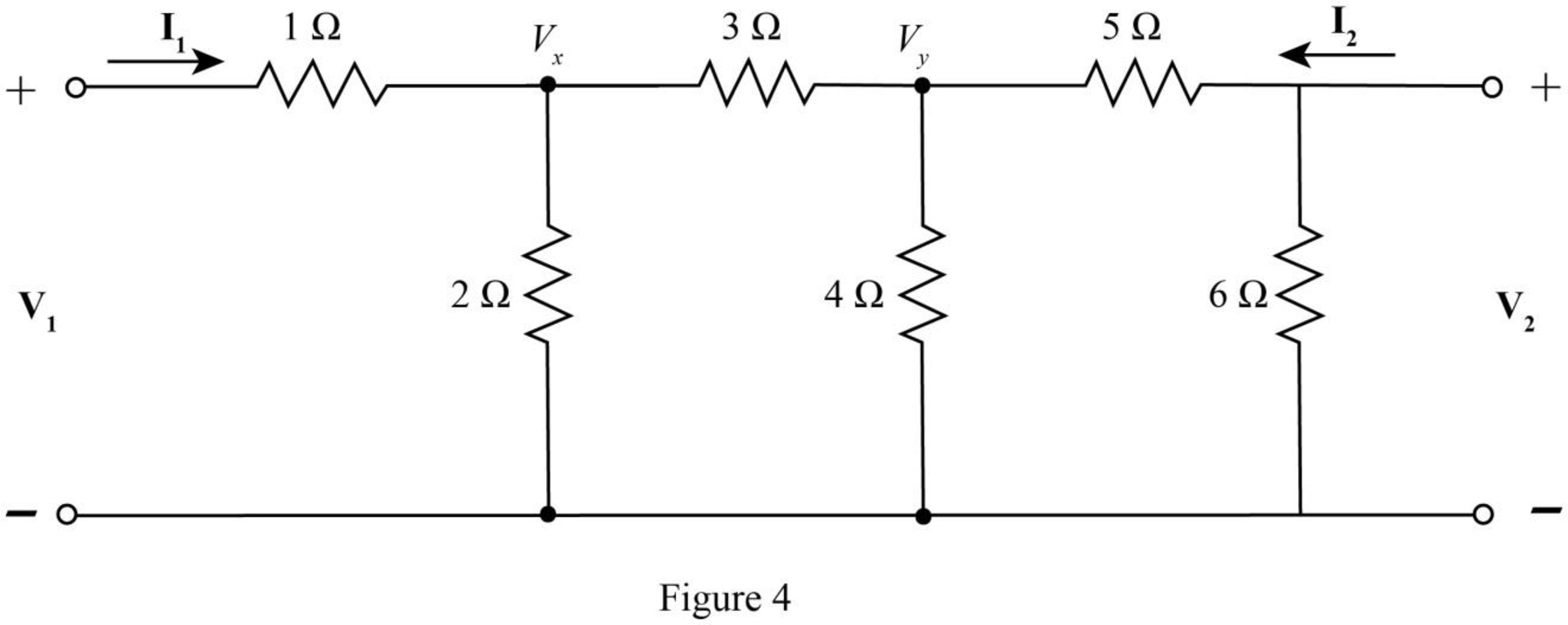
The nodal equation at node
The nodal equations at node
Substitute
Substitute
The current
Substitute
The current
Substitute
The
Here,
Compare equation (16) with equation (18).
Compare equation (17) with equation (19).
The determinant of the matrix
Substitute
The relation between
Substitute
Within the limits of error, the values have been verified.
Conclusion:
Therefore, the values have been verified.
Want to see more full solutions like this?
Chapter 16 Solutions
Loose Leaf for Engineering Circuit Analysis Format: Loose-leaf
Additional Engineering Textbook Solutions
Vector Mechanics For Engineers
Mechanics of Materials (10th Edition)
Electric Circuits. (11th Edition)
SURVEY OF OPERATING SYSTEMS
Modern Database Management
Starting Out with C++ from Control Structures to Objects (9th Edition)


- 3-3) Similar to Lathi & Ding prob. 3.3-7. The signals in the figure below are modulated signals with carrier cos(5t). Find the Fourier transforms of these signals using the appropriate properties of the Fourier transform and text Table 3.1. The sketch the magnitude and phase spectra for figure parts (a) and (b). Hint: these functions can be expressed in the form g(t) cos(2лfot) (a) 1 1 2π www. σπ (b) (c) όπarrow_forward3-1) Similar to Lathi & Ding prob. 3.1-1. Use direct integration to find the Fourier transforms of the signals shown below. a) g₁(t) = II(t − 2) + 2 exp (−3|t|) b) g(t) = d(t+2)+3e¯u (t − 2)arrow_forward3-2) Lathi & Ding prob. 3.1-5. From the definition in eq. 3.1b, find the inverse Fourier transforms of the spectra in the figure below. G(f) COS лf 10 (a) G(f) 1 -B B (b)arrow_forward
- Construct a battery pack to deliver 360V and 450-mile range for a vehicle that consumes 200 Wh/mile, from prismatic cells with 25Ah and 3.6 V. Physical dimensions of the cell are 0.5 cm thickness, 20 cm width and 40 cm length. a) Report configuration of the battery pack. 10-points b) Resistance of each cell is 0.05 Ohm, calculate the total internal resistance of the battery pack. 10-points c) Calculate the voltage drop during discharge when the battery is discharged at 100A. 10-points d) Calculate the amount of anode and cathode to build a prismatic cell with 25Ah capacity. Assume the cell chemistry as: Si anode and [Li(Ni1/3Co1/3Mn1/3)O2] cathode. Atomic weight of elements: Li=7, Si = 28, Ni=58, Co=59, Mn=55, O=16, 10-points e) Calculate the theoretical specific energy (Wh/kg) and practical energy density (Wh/liter) of the battery pack. 10-points f) Calculate the thickness on anode and cathode coating assuming each electrode has 30%…arrow_forwardI need help with this problem and an explanation of the solution for the image described below. (Introduction to Signals and Systems)arrow_forwardDesign a battery pack for an electric bike that consumes in average 10Wh/mile and drive 30 miles per charge. The battery state of charge window is 80%. Design the battery by using new commercial cylindrical cells with 20mm diameter and 80mm height. The battery is constructed based on graphite anode C6 and cathode Li(Ni0.8Co0.15Al0,05)O2 that provides 3.75V at the cell level and 10Ah capacity. Density of anode is 2.2 g/cm3 and density of cathode is 4.5 g/cm3. Report on the battery pack configuration if the required battery pack voltage is 75 volts. If the thickness of anode and cathode is limited to 130 microns (130 x 10-4 cm) calculate the total electrode surface area in each cell. Assume the porosity of electrodes are 30%. Calculate the weight of active materials (anode and cathode) in grams and the total current collector’s and electrolyte membrane areas in (cm2).arrow_forward
 Power System Analysis and Design (MindTap Course ...Electrical EngineeringISBN:9781305632134Author:J. Duncan Glover, Thomas Overbye, Mulukutla S. SarmaPublisher:Cengage Learning