
Videos
The required
Answer to Problem 39E
The required
Explanation of Solution
Given data:
The angular frequency is
Calculation:
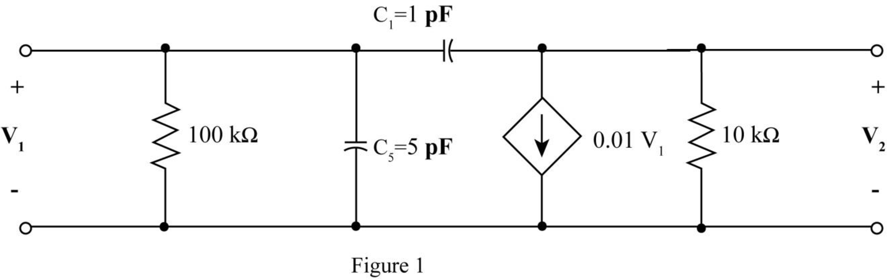
The given diagram is shown in Figure 1.
The conversion from
The conversion from
The conversion from
The conversion from
The conversion from
The capacitive reactance of
Substitute
The capacitive reactance of
Substitute
The modified diagram is shown in Figure 2.
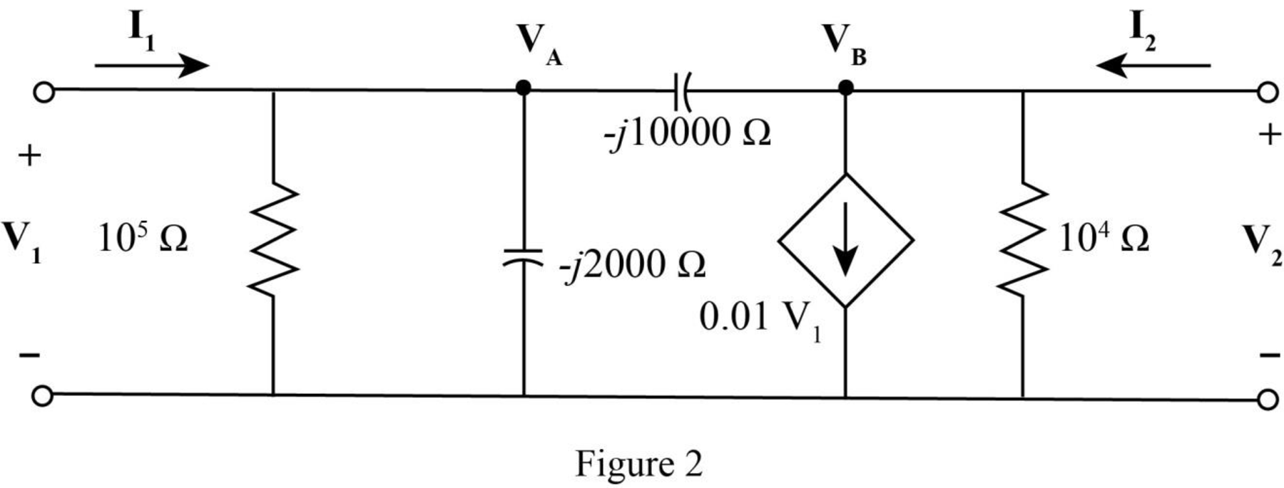
Apply KCL at node
Apply KCL at node
The standard equation for admittance parameters is,
Write equation (1) and equation (2) in matrix form.
Write equation (3) and equation (4) in matrix form
Compare equation (5) with equation (6).
The voltage expression
Substitute
The voltage expression
Substitute
The standard equation for impedance parameter are,
Compare equation (7) with equation (9).
Compare equation (8) with equation (10).
The
Conclusion:
Therefore, the required
Want to see more full solutions like this?
Chapter 16 Solutions
Loose Leaf for Engineering Circuit Analysis Format: Loose-leaf


- 1° ⑤ Aa "Human-written solution required" 2. Using the characteristics of Fig. 6.11, determine ID for the following levels of VGs (with VDS > VP): a. VGs = 0V. b. VGs=-1 V. c. VGs -1.5 V. d. VGS -1.8 V. e. VGS = -4 V. f. VGs=-6V. 3. Using the results of problem 2 plot the transfer characteristics of ID vs. VGS- 4. a. Determine Vps for VGs = 0V and Ip = 6 mA using the characteristics of Fig. 6.11. b. Using the results of part (a), calculate the resistance of the JFET for the region Ip = 0 to 6 mA for VGs =0V. c. Determine Vps for VGS = -1 V and ID = 3 mA. d. Using the results of part (c), calculate the resistance of the JFET for the region ID = 0 to 3 mA for VGs -1 V. e. Determine Vps for VGs = -2 V and ID = 1.5 mA. f. Using the results of part (e), calculate the resistance of the JFET for the region ID = 0 to 1.5 mA for VGS-2 V. g. Defining the result of part (b) as ro, determine the resistance for VGs -1 V using Eq. (6.1) and compare with the results of part (d). h. Repeat part (g)…arrow_forward① Esterfication + R'on R Hydrolysis OH Alcohol A. 0-R Carboxylic Acid Ester NOD-10arrow_forward4. a. Determine VDs for VGS = 0 V and ID = 6 mA using the characteristics of Fig. 6.11. b. Using the results of part (a), calculate the resistance of the JFET for the region ID = 0 to 6 mA for VGS = 0 V. c. Determine VDs for VGS = -1 V and ID = 3 mA. d. Using the results of part (c), calculate the resistance of the JFET for the region ID = 0 to 3 mA for VGS = -1 V. e. Determine VDs for VGS = -2 V and ID = 1.5 mA. f. Using the results of part (e), calculate the resistance of the JFET for the region ID = 0 to 1.5 mA for VGS = -2 V. g. Defining the result of part (b) as ro, determine the resistance for VGS = -1 V using Eq. (6.1) and compare with the results of part (d). h. Repeat part (g) for VGS = -2 V using the same equation, and compare the results with part (f). i. Based on the results of parts (g) and (h), does Eq. (6.1) appear to be a valid approximation?arrow_forward
- A. Using D flip-flops, design a logic circuit for the finite-state machine described by the state assigned table in Fig. 1. Present Next State State Output x=0 x=1 Y2Y1 Y2Y1 YY Z 00 00 01 0 01 10 11 888 00 10 0 00 10 1 00 10 1 Fig. 1arrow_forwardAthree phase a.c. distributor AB has: A B C The distance from A to B is 500 m. The distance from A to C is 800 m. The impedance of each section is (6+j 8) /km. The voltage at the far end is maintained at 250 volt. Find: sending voltage, sending current, supply power factor and 80A 60 A total voltage drop. 0.8 lag. P.f 0.6 lead. p.farrow_forwardengineering electromagnetics Subjectarrow_forward
- a ADI ADI b Co ADDS D Fig.(2) 2-For resistive load, measure le output voltage by using oscilloscope; then sketch this wave. 3- Measure the average values ::f V₁ and IL: 4- Repeat steps 2 & 3 but for PL load.arrow_forwardDetermine the type of media In a certain medium with µ = o, & = 40 H = 12ely sin(x x 10% - By) a, A/m A plane wave propagating through a medium with ɛ, = 8, μ, = 2 has E = 0.5 3sin(10°t - Bz) a, V/m. Determine In a certain medium - E = 10 cos (2 x 10't ẞx)(a, + a.) V/m If μ == 50μo, & = 2ɛ, and o = 0, In a medium, -0.05x E=16e sin (2 x 10% -2x) a₂ V/marrow_forward"How can I know if it's lossless or lossy? Is there an easy way?" A plane wave propagating through a medium with &,,-8 μr = 2 nas: E = 0.5 ej0.33z sin (10' t - ẞz) ax V/m. A plane wave in non- · (Mr=1) has: magnetic medium E. 50 sin (10st + 27 ) ay v/m =arrow_forward
- a A DI AD: AD, b C ADDS AD Fig.(2) LOIT 4-Draw the waveform for the c:t. shown in fig.(2) but after replaced Di and D3 by thyristors with a 30° and a2 #90°.arrow_forwarda b C ADDS D Fig.(2) L O 5- Draw the waveform for the cct. shown in fig.(2) but after replace the 6-diodes by 6- thyristor.arrow_forwardThe magnetic field component of an EM wave propagating through a nonmagnetic medium (po) is = Determine: H=25 sin (2 x 10't + 6x) a, mA/m (a) The direction of wave propagation. (b) The permittivity of the medium. (c) The electric field intensity.arrow_forward
 Introductory Circuit Analysis (13th Edition)Electrical EngineeringISBN:9780133923605Author:Robert L. BoylestadPublisher:PEARSON
 Delmar's Standard Textbook Of ElectricityElectrical EngineeringISBN:9781337900348Author:Stephen L. HermanPublisher:Cengage Learning
 Programmable Logic ControllersElectrical EngineeringISBN:9780073373843Author:Frank D. PetruzellaPublisher:McGraw-Hill Education
 Fundamentals of Electric CircuitsElectrical EngineeringISBN:9780078028229Author:Charles K Alexander, Matthew SadikuPublisher:McGraw-Hill Education
 Electric Circuits. (11th Edition)Electrical EngineeringISBN:9780134746968Author:James W. Nilsson, Susan RiedelPublisher:PEARSON
 Engineering ElectromagneticsElectrical EngineeringISBN:9780078028151Author:Hayt, William H. (william Hart), Jr, BUCK, John A.Publisher:Mcgraw-hill Education,