
Videos
(a)
The determinant and the input impedance of the network when
(a)
Answer to Problem 7E
The determinant of the network is
Explanation of Solution
Given data:
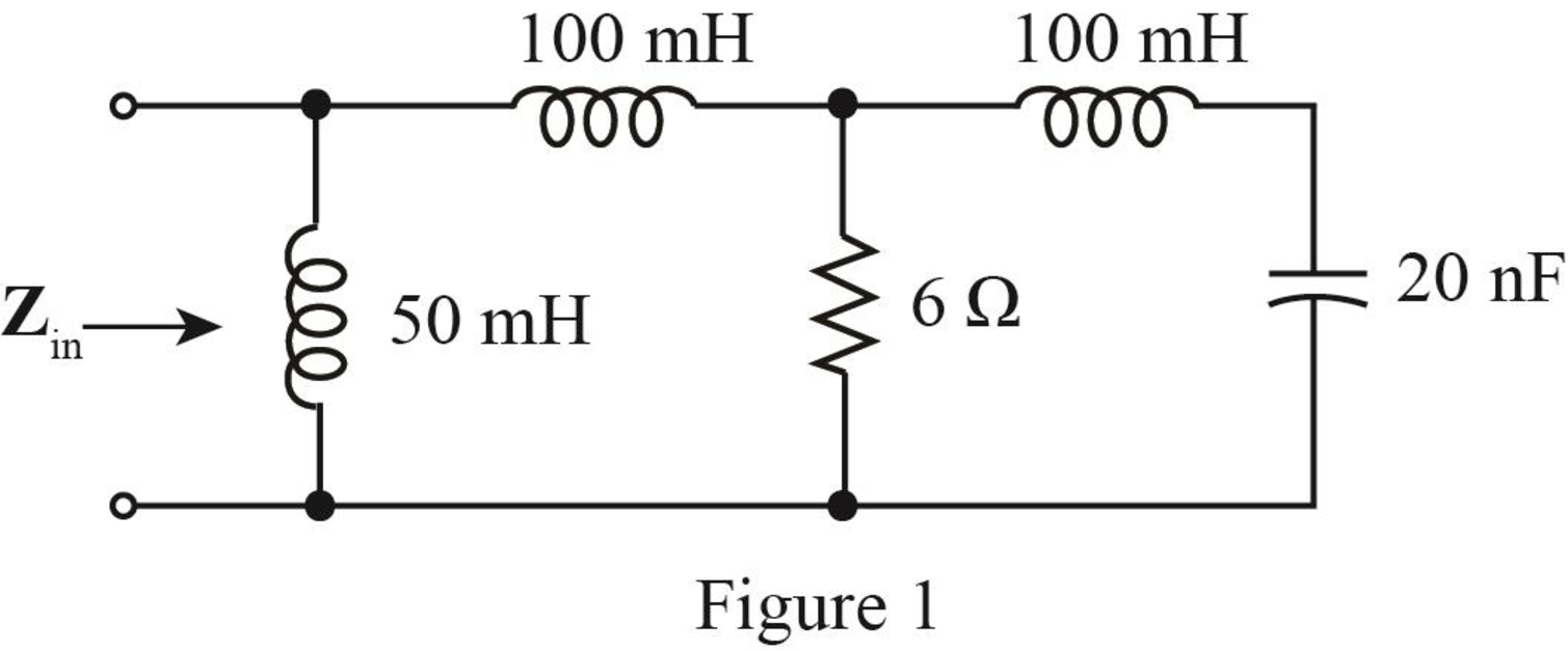
The given diagram is shown in Figure 1.
Calculation:
The conversion of
The conversion of
The conversion of
The conversion of
The conversion of
The conversion of
For
The admittance of inductor is given by,
Substitute
For
The admittance of inductor is given by,
Substitute
For
The admittance of capacitor is given by,
Substitute
For
The admittance of inductor is given by,
Substitute
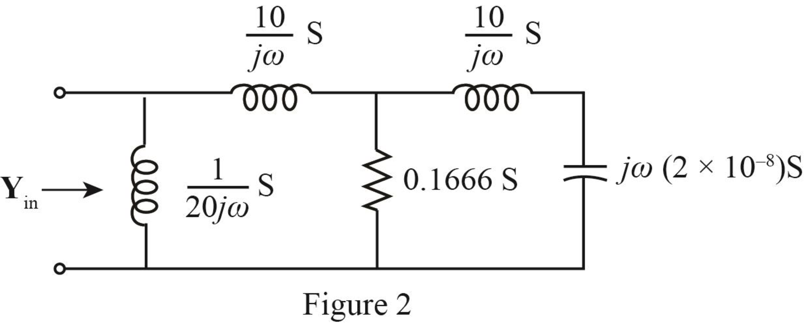
The required diagram is shown in Figure 2.
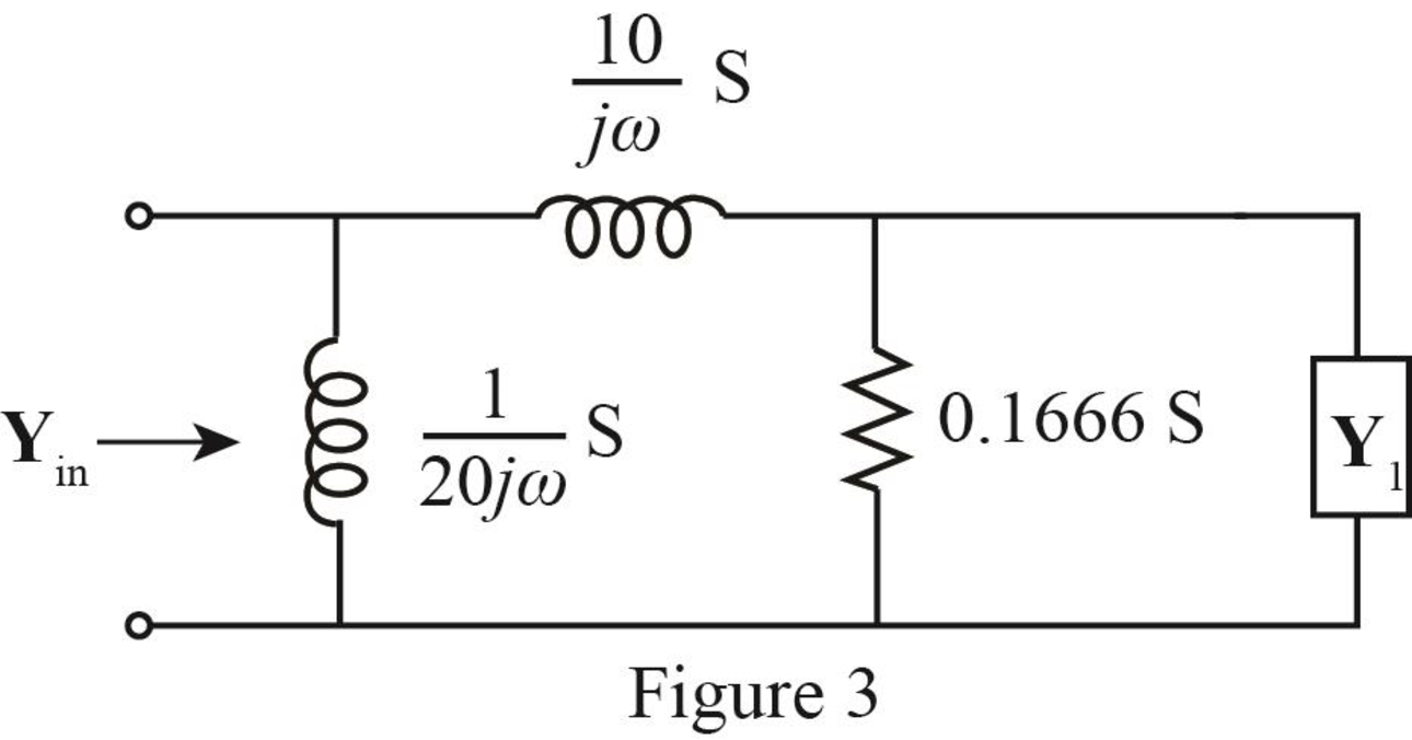
The inductor and the capacitor are in series.
The modified diagram is shown in Figure 3.
The expression for
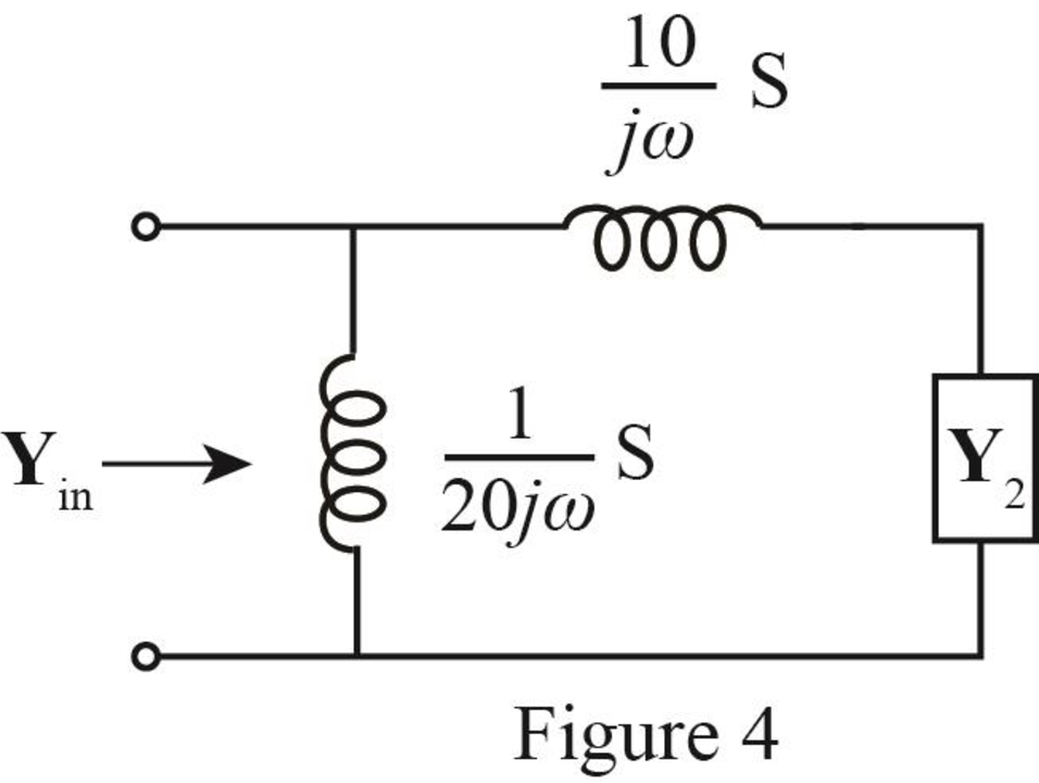
The admittance
The modified diagram is shown in Figure 4.
The expression of
The admittance
The modified diagram is shown in Figure 5.
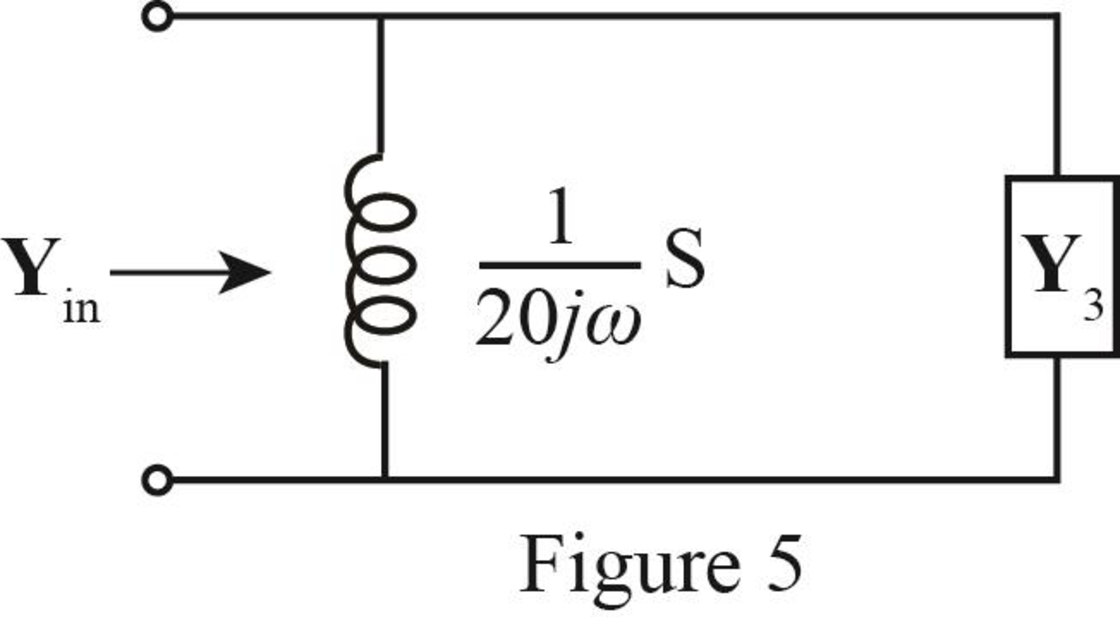
The expression of
Substitute
Further solve as,
The input admittance is the parallel combination of the inductor and
The expression of the input admittance
Substitute
Substitute
Mark the node voltages as
The required diagram is shown in Figure 6.
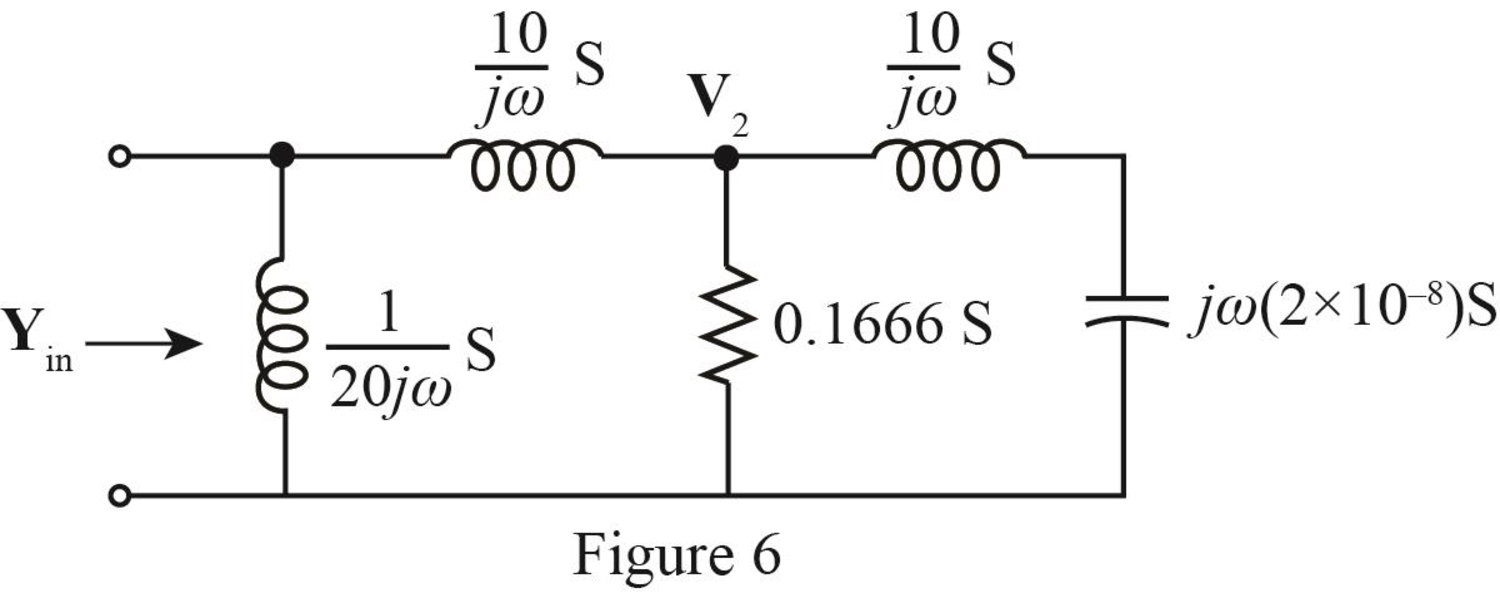
The equation at node voltage
The equation at node voltage
Substitute
Write equation (1) and (2) in matrix form.
The determinant of the given circuit is given by,
Further solve as,
Conclusion:
Therefore, the determinant of the network is,
(b)
The voltage across the current source.
(b)
Answer to Problem 7E
The voltage across the current source is
Explanation of Solution
Given data:
The value of the current source is,
The frequency is
Calculation:
The required diagram is shown in Figure 7.
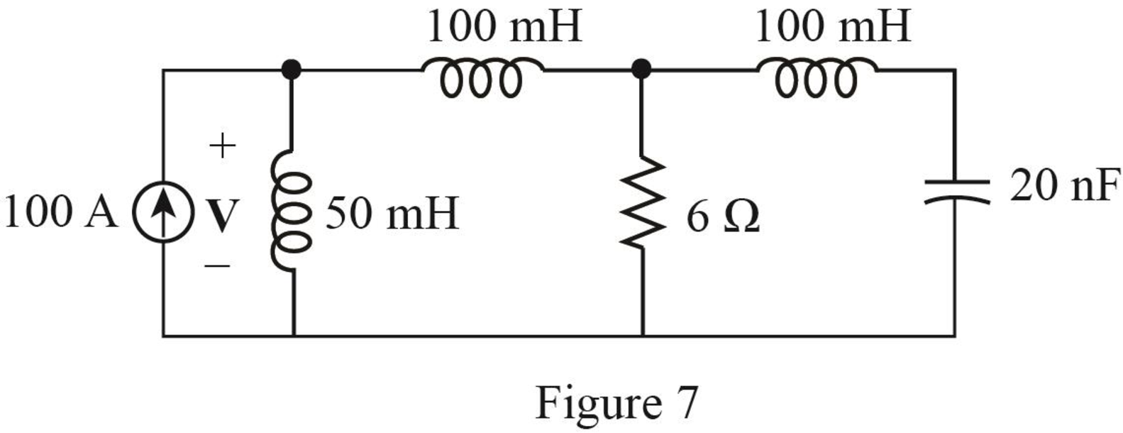
The expression for the voltage across current source is given by,
Here,
Substitute
Conclusion:
Therefore, the voltage across the current source is
Want to see more full solutions like this?
Chapter 16 Solutions
Loose Leaf for Engineering Circuit Analysis Format: Loose-leaf


- Q9 A single-phase transformer, 2500 / 250 V, 50 kVA, 50 Hz has the following parameters, the Primary and secondary resistances are 0.8 ohm and 0.012 ohm respectively, the primary and secondary reactance are 4 ohm and 0.04 ohm respectively and the transformer gives 96% maximum efficiency at 75% full-load. The magnetizing component of-load current is 1.2 A on 2500 V side. 1- Draw the equivalent circuit referred to primary (H.V side) and inserts all the values in it 2- Find out Ammeter, voltmeter and wattmeter readings on open-circuit and short-circuit test. If supply is given to 2500 V side in both cases. Ans. O.C. Test (Vo= 2500 V, lo=1.24 A, Wo=781.25 w) S.C. Test (Vsc =164.924 V, Isc =20 A, Wsc =800 w )arrow_forwardQ2-A)- Enumerate the various losses in transformer. Explain how each loss varies with (Load current, supply voltage). B)- Draw the pharos diagram at load on primary side.arrow_forwardQ2- What are the parameters and loss that can be determined during open-circuit test of singlephase transformer. Draw the circuit diagram of open-circuit test and explain how can you calculate the Parameters and loss.arrow_forward
- Q2-Drive the condition of maximum efficiency of single-phase transformer. Q1- A 5 KVA, 500/250 V ,50 Hz, single phase transformer gave the following reading: O.C. Test: 250 V,2 A, 50 W (H.V. side open) S.C. Test: 25 V10 A, 60 W (L.V. side shorted) Determine: i) The efficiency on full load, 0.8 lagging p.f. ii) Draw the equivalent circuit referred to primary and insert all the values it.arrow_forwardQ2- Describe various losses in transformer. Explain how each loss varies with load current, supply voltagearrow_forwardQ1-A 12 KVA, 440/ 220 V, 50 Hz single phase transformer has 275 secondary turns. The no load current of transformer is 2A at power factor 0.375 when connected to 220 V, 50 Hz supply. The full load copper loss is 198.3 watt. Calculate a) Maximum value of flux in the core. b) Maximum efficiency at 0.8 lagging p.f c) KVA supply at maximum efficiencyarrow_forward
- Q1- A 5 KVA, 240/120 volt, single-phase transformer supplies rated current to a load at 120 V. Determine the magnitude of the load impedance as seen from the input terminals of the transformer. Ans. 11.52arrow_forwardQ1- A single phase transformer consumes 2 A on no load at p.f. 0.208 lagging. The turns ratio is 2/1 (step down). If the loads on the secondary is 25 A at a p.f. 0.866 lagging. Find the primary current and power factor.arrow_forwardI am seeking ideas or references regarding the auxiliary power output for a trolley. I’ve encountered difficulties finding information online about the power output for lights, buzzers, and speakers. Specifically, I am interested in the following questions: How many lights, buzzers, and speakers can a trolley approximately 48 feet in length accommodate?How can I determine their rated power?Any guidance or resources you can provide would be greatly appreciated. Thank you!arrow_forward
- 5. Three single-phase transformers rated at 250 kVA, 7200 V/600 V, 60 Hz, are connected in wye-delta on a 12470 V, 3-phase line. If the load is 450 kVA, calculate the following currents: (1) In the incoming and outgoing transmission lines (2) In the primary and secondary windings (3) If this transformer is used to raise the voltage of a 3-phase, 600 V line to 7.2 kV. (a) How must they be connected? (b) Calculate the line currents for a 600 kVA load. (c) Calculate the corresponding primary and secondary currents.arrow_forwardplease answer handwritten not chatgbtarrow_forwardplease answer handwritten not chatgbtarrow_forward
 Introductory Circuit Analysis (13th Edition)Electrical EngineeringISBN:9780133923605Author:Robert L. BoylestadPublisher:PEARSON
 Delmar's Standard Textbook Of ElectricityElectrical EngineeringISBN:9781337900348Author:Stephen L. HermanPublisher:Cengage Learning
 Programmable Logic ControllersElectrical EngineeringISBN:9780073373843Author:Frank D. PetruzellaPublisher:McGraw-Hill Education
 Fundamentals of Electric CircuitsElectrical EngineeringISBN:9780078028229Author:Charles K Alexander, Matthew SadikuPublisher:McGraw-Hill Education
 Electric Circuits. (11th Edition)Electrical EngineeringISBN:9780134746968Author:James W. Nilsson, Susan RiedelPublisher:PEARSON
 Engineering ElectromagneticsElectrical EngineeringISBN:9780078028151Author:Hayt, William H. (william Hart), Jr, BUCK, John A.Publisher:Mcgraw-hill Education,