
Videos
(a)
To construct: The table for the state of each transistor.
To find: The output voltage
(a)
Answer to Problem 16.62P
The value of the output voltages is obtained and is shown in Table 2
Explanation of Solution
Calculation:
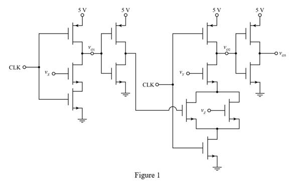
The given diagram is shown in Figure 1
The given table is shown in Table 1
Table 1
| State | CLK | |||
For state 1
The input clock signal input X, Y and Z are at logic zero and the logic function of the output voltage
Substitute
From the circuit the NMOS device with the input
The expression for the logic function of the output voltage
Substitute
The logic function of the output voltage
Substitute
For state 2.
All the inputs are at logic 1.
Substitute
Substitute
Substitute
For state 3.
All the inputs are at logic 0.
Substitute
Substitute
Substitute
For state 4.
The input clock,
Substitute
Substitute
Substitute
For state 5.
All the inputs are at logic zero.
Substitute
Substitute
Substitute
For state 6.
The input clock,
Substitute
Substitute
Substitute
The table for the state of the transistors and the output voltage is shown in table below.
The required table is shown in Table 2
Table 2
| State | CLK | ||||||
The table for the state of the transistor is shown below.
Conclusion:
Therefore, the value of the output voltages is obtained and is shown in Table 2
(b)
The logic function that the circuit implements.
(b)
Answer to Problem 16.62P
The logic that the circuit performs is
Explanation of Solution
Calculation:
The expression for the output voltage
Substitute
Conclusion:
Therefore, the logic that the circuit performs is
Want to see more full solutions like this?
Chapter 16 Solutions
MICROELECT. CIRCUIT ANALYSIS&DESIGN (LL)


- If C is the circle |z|=4 evaluate f f (z)dz for each of the following functions using residue. 1 f(z) = z(z²+6z+4)arrow_forwardIf C is the circle |z|=4 evaluate ff(z)dz for each of the following functions using residue. f(z) z(z²+6z+4)arrow_forwardDetermine X(w) for the given function shown in Figure (1) by applying the differentiation property of the Fourier Transform. 1 x(t) Figure (1) -2 I -1 1 2arrow_forward
- Please solve it by explaining the steps. I am trying to prepare for my exam tomorrow, so any tips and tricks to solve similar problems are highly appreciated. Plus, this is a past exam I am using to prepare.arrow_forwardPlease solve it by explaining the steps. I am trying to prepare for my exam tomorrow, so any tips and tricks to solve similar problems are highly appreciated. Plus, this is a past exam I am using to prepare.arrow_forwardPlease solve it by explaining the steps. I am trying to prepare for my exam tomorrow, so any tips and tricks to solve similar problems are highly appreciated. Plus, this is a past exam I am using to prepare.arrow_forward
- Please solve it by explaining the steps. I am trying to prepare for my exam tomorrow, so any tips and tricks to solve similar problems are highly appreciated. Plus, this is a past exam I am using to prepare.arrow_forwardPlease solve it by explaining the steps. I am trying to prepare for my exam tomorrow, so any tips and tricks to solve similar problems are highly appreciated. Plus, this is a past exam I am using to prepare.arrow_forwardPlease solve it by explaining the steps. I am trying to prepare for my exam tomorrow, so any tips and tricks to solve similar problems are highly appreciated. Plus, this is a past exam I am using to prepare.arrow_forward
- Please solve it by explaining the steps. I am trying to prepare for my exam tomorrow, so any tips and tricks to solve similar problems are highly appreciated. Plus, this is a past exam I am using to prepare.arrow_forwardPlease solve it by explaining the steps. I am trying to prepare for my exam tomorrow, so any tips and tricks to solve similar problems are highly appreciated. Plus, this is a past exam I am using to prepare.arrow_forwardPlease solve it by explaining the steps. I am trying to prepare for my exam tomorrow, so any tips and tricks to solve similar problems are highly appreciated. Plus, this is a past exam I am using to prepare.arrow_forward
 Introductory Circuit Analysis (13th Edition)Electrical EngineeringISBN:9780133923605Author:Robert L. BoylestadPublisher:PEARSON
 Delmar's Standard Textbook Of ElectricityElectrical EngineeringISBN:9781337900348Author:Stephen L. HermanPublisher:Cengage Learning
 Programmable Logic ControllersElectrical EngineeringISBN:9780073373843Author:Frank D. PetruzellaPublisher:McGraw-Hill Education
 Fundamentals of Electric CircuitsElectrical EngineeringISBN:9780078028229Author:Charles K Alexander, Matthew SadikuPublisher:McGraw-Hill Education
 Electric Circuits. (11th Edition)Electrical EngineeringISBN:9780134746968Author:James W. Nilsson, Susan RiedelPublisher:PEARSON
 Engineering ElectromagneticsElectrical EngineeringISBN:9780078028151Author:Hayt, William H. (william Hart), Jr, BUCK, John A.Publisher:Mcgraw-hill Education,