
Applied Statics and Strength of Materials (6th Edition)
6th Edition
ISBN: 9780133840544
Author: George F. Limbrunner, Craig D'Allaird, Leonard Spiegel
Publisher: PEARSON
expand_more
expand_more
format_list_bulleted
Concept explainers
Videos
Textbook Question
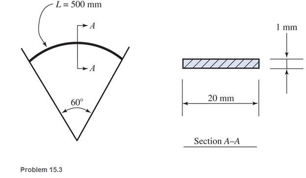
Chapter 15, Problem 15.3P
A
Expert Solution & Answer

Learn your wayIncludes step-by-step video

schedule04:29
Students have asked these similar questions
!
Required information
A telephone cable is clamped at A to the pole AB. The tension in the left-hand portion of the cable is given to be
T₁ = 815 lb.
A
15°
25°
B
T₂
Using trigonometry, determine the required tension T₂ in the right-hand portion if the resultant R of the forces exerted by the cable at
A is to be vertical.
The required tension is
lb.
What are examples of at least three (3) applications of tolerance fitting analysis.
The primary material used in the production of glass products is silica sand.
True or False
Chapter 15 Solutions
Applied Statics and Strength of Materials (6th Edition)
Ch. 15 - A 14 in.-diameter aluminum rod is bent into a...Ch. 15 - 15.2 Calculate the maximum bending stress produced...Ch. 15 - A 500 -mm-long steel bar having a cross section of...Ch. 15 - 15.4 An aluminum wire has a diameter of in....Ch. 15 - 15.5 A -in.-wide by in.-thick board is bent to a...Ch. 15 - 15.6 A Douglas fir beam is in. wide and in. deep....Ch. 15 - Prob. 15.7PCh. 15 - For Problems 15.7 through 15.14, use the formula...Ch. 15 - For Problems 15.7 through 15.14, use the formula...Ch. 15 - For Problems 15.7 through 15.14, use the formula...
Ch. 15 - For Problems 15.7 through 15.14, use the formula...Ch. 15 - For Problems 15.7 through 15.I4, use the formula...Ch. 15 - For Problems 15.7 through 15.14, use the formula...Ch. 15 - For Problems 15.7 through 15.14, use the formula...Ch. 15 - For Problems 15.15 through 15.26, use the...Ch. 15 - For Problems 15.15 through 15.26, use the...Ch. 15 - For Problems 15.15 through 15.26, use the...Ch. 15 - For Problems 15.15 through 15.26, use the...Ch. 15 - For Problems 15.15 through 15.26, use the...Ch. 15 - For Problems 15.15 through 15.26, use the...Ch. 15 - For Problems 15.15 through 15.26, use the...Ch. 15 - For Problems 15.15 through 15.26, use the...Ch. 15 - For Problems 15.15 through 15.26, use the...Ch. 15 - For Problems 15.15 through 15.26, use the...Ch. 15 - For Problems 15.15 through 15.26, use the...Ch. 15 - For Problems 15.15 through 15.26, use the...Ch. 15 - 15.27 Draw the moment diagram by parts for the...Ch. 15 - 15.28 Draw the moment diagram by parts for the...Ch. 15 - 15.29 Draw the moment diagram by parts for the...Ch. 15 - 15.30 For the beam shown, draw the conventional...Ch. 15 - For Problems 15.31 through 15.43, use the...Ch. 15 - For Problems 15.31 through 15.43, use the...Ch. 15 - For Problems 15.31 through 15.43, use the...Ch. 15 - For Problems 15.31 through 15.43, use the...Ch. 15 - For Problems 15.31 through 15.43, use the...Ch. 15 - For Problems 15.31 through 15.43, use the...Ch. 15 - For Problems 15.31 through 15.43, use the...Ch. 15 - For Problems 15.31 through 15.43, use the...Ch. 15 - For Problems 15.31 through 15.43, use the...Ch. 15 - For Problems 15.31 through 15.43, use the...Ch. 15 - For Problems 15.31 through 15.43, use the...Ch. 15 - For Problems 15.31 through 15.43, use the...Ch. 15 - For Problems 15.31 through 15.43, use the...Ch. 15 - 15.49 If the elastic limit of a steel wire is...Ch. 15 - 15.50 Calculate the bending moment required to...Ch. 15 - 15.51 A 6-ft-long cantilever beam is subjected to...Ch. 15 - 15.52 A structural steel wide-flange section is...Ch. 15 - 15.53 A simply supported structural steel...Ch. 15 - 15.54 A structural steel wide-flange shape is...Ch. 15 - A solid, round simply supported steel shaft is...Ch. 15 - Using the moment-area method, check the...Ch. 15 - 15.57 A 1-in.-diameter steel bar is 25 ft long and...Ch. 15 - 15.58 A 102-mm nominal diameter standard-weight...Ch. 15 - I 5.59 Compute the maximum deflection for the...Ch. 15 - An 8-in-wide by 12-in-deep redwood timber beam...Ch. 15 - 15.61 A solid steel shaft 3 in. in diameter and 20...Ch. 15 - 15.62 For the beam shown, draw the conventional...Ch. 15 - 15.63 Rework Problem 15.62 with concentrated loads...Ch. 15 - 15.64 A solid steel shaft 3 in. in diameter and 20...Ch. 15 - 15.65 A structural steel wide-flange section is...Ch. 15 - 15.66 A 6-in.-by-10-in, hem-fir timber beam (S4S)...Ch. 15 - 15.67 A simply supported structural steel...Ch. 15 - Calculate the maximum permissible span length for...Ch. 15 - 15.69 A structural steel wide-flange section 10 ft...Ch. 15 - 15.70 A structural steel wide-flange section...Ch. 15 - 15.71 Determine the deflection at point C and...Ch. 15 - 15.72 Calculate the deflection midway between the...Ch. 15 - 15.73 Derive an expression for the maximum...Ch. 15 - 15.74 Derive an expression for the maximum...
Additional Engineering Textbook Solutions
Find more solutions based on key concepts
How does a computers main memory differ from its auxiliary memory?
Java: An Introduction to Problem Solving and Programming (8th Edition)
ICA 8-54
When we drive our car at 100 feet per second [ft/s], we measure an aerodynamic force (called drag) of ...
Thinking Like an Engineer: An Active Learning Approach (4th Edition)
Write an SQL statement to display the name, breed, and type for all pets that are not of type Cat, Dog, or Fish...
Database Concepts (8th Edition)
Suppose your program contains the following type definitions: struct Box { string name; int number; Box next; }...
Problem Solving with C++ (10th Edition)
In the chapter, we introduced a machine instruction of the form ODROS. Suppose we extended this form to OxDRXS,...
Computer Science: An Overview (13th Edition) (What's New in Computer Science)
How do you clear the contents of a TextBox control?
Starting Out With Visual Basic (8th Edition)
Knowledge Booster


Learn more about
Need a deep-dive on the concept behind this application? Look no further. Learn more about this topic, mechanical-engineering and related others by exploring similar questions and additional content below.Similar questions
- Which one of the following is the most common polymer type in fiber-reinforced polymer composites? thermosets thermoplastics elastomers none of the abovearrow_forwardA pattern for a product is larger than the actual finished part. True or Falsearrow_forwardIn the lost foam process, the pattern doesn’t need to be removed from the mold. True or Falsearrow_forward
- Tempering eliminates internal stresses in glass. True or Falsearrow_forwardThermoset polymers can be recycled with little to no degradation in properties. True or Falsearrow_forwardTwo forces are applied as shown to a hook support. The magnitude of P is 38 N. 50 N 25° DG a 터 Using trigonometry, determine the required angle a such that the resultant R of the two forces applied to the support will be horizontal. The value of a isarrow_forward
- No chatgpt pls will upvotearrow_forward101 the three shafts if the diameter ratio is 2 (D/d = 2)? Ans. na, tension = 1.21, na, bending = 1.19, na, torsion = 1.17. 6.32 A material with a yield strength of S₁ = 350 MPa is subjected to the stress state shown in Sketch c. What is the factor of safety based on the maximum shear stress and distortion energy theories? Ans. For MSST, n, = 11.67. 50 MPa 85 MPa 20 MPa 70 MPa Sketch c, for Problems 6.32 and 6.33arrow_forwardCan you draw the left view of the first orthographic projectionarrow_forward
- Important: I've posted this question twice and received incorrect answers. I've clearly stated that I don't require AI-generated working out. I need a genuine, expert-written solution with proper working. If you can't provide that, refer this question to someone who can please!. Note: Please provide a clear, step-by-step handwritten solution (no AI involvement). I require an expert-level answer and will assess it based on quality and accuracy with that I'll give it a thumbs up or down!. Hence, refer to the provided image for clarity. Double-check everything for correctness before submitting. Thank you!arrow_forwardNote: Please provide a clear, step-by-step simplified handwritten working out (no explanations!), ensuring it is done without any AI involvement. I require an expert-level answer, and I will assess and rate based on the quality and accuracy of your work and refer to the provided image for more clarity. Make sure to double-check everything for correctness before submitting appreciate your time and effort!. Question:arrow_forwardNote: Please provide a clear, step-by-step simplified handwritten working out (no explanations!), ensuring it is done without any AI involvement. I require an expert-level answer, and I will assess and rate based on the quality and accuracy of your work and refer to the provided image for more clarity. Make sure to double-check everything for correctness before submitting appreciate your time and effort!. Question: If the flow rate through the system below is 0.04m3s-1, find the difference in elevation H of the two reservoirs.arrow_forward
arrow_back_ios
SEE MORE QUESTIONS
arrow_forward_ios
Recommended textbooks for you
 Mechanics of Materials (MindTap Course List)Mechanical EngineeringISBN:9781337093347Author:Barry J. Goodno, James M. GerePublisher:Cengage Learning
Mechanics of Materials (MindTap Course List)
Mechanical Engineering
ISBN:9781337093347
Author:Barry J. Goodno, James M. Gere
Publisher:Cengage Learning
Types of Manufacturing Process | Manufacturing Processes; Author: Magic Marks;https://www.youtube.com/watch?v=koULXptaBTs;License: Standard Youtube License