
Applied Statics and Strength of Materials (6th Edition)
6th Edition
ISBN: 9780133840544
Author: George F. Limbrunner, Craig D'Allaird, Leonard Spiegel
Publisher: PEARSON
expand_more
expand_more
format_list_bulleted
Concept explainers
Videos
Textbook Question
Chapter 15, Problem 15.3P
A
Expert Solution & Answer

Learn your wayIncludes step-by-step video

schedule04:29
Students have asked these similar questions
a 80 mm wide and 300 mm high simply supported bean has a length of 7.4 m and supports a concentrated load of 7.2 kN acting at the midspan. Find the maximum shear stress and maximum bending stress.
A shaft used in an aircraft engine is 50 mm diameter, the maximum allowable shear stress is
84 MN/m². Find the torsional strength of the shaft. If the shaft now has a hole bored in it,
find the percentage reductions in strength and mass.
a. If the hole is 40 mm diameter
b. If the hole is 25 mm diameter.
For the beam shown, there is a roller at 1.5 feet from the left and a pinned support at the far-right end. Two loads are applied: a 450-kip vertical load and a 15 kip*ft moment. The cross-sectional shape of the beam is shown on the right. What is the maximum stress on this beam? Note: A kip is a kilopound.
Chapter 15 Solutions
Applied Statics and Strength of Materials (6th Edition)
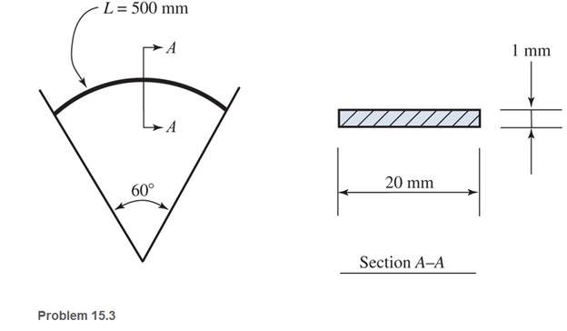
Ch. 15 - A 14 in.-diameter aluminum rod is bent into a...Ch. 15 - 15.2 Calculate the maximum bending stress produced...Ch. 15 - A 500 -mm-long steel bar having a cross section of...Ch. 15 - 15.4 An aluminum wire has a diameter of in....Ch. 15 - 15.5 A -in.-wide by in.-thick board is bent to a...Ch. 15 - 15.6 A Douglas fir beam is in. wide and in. deep....Ch. 15 - Prob. 15.7PCh. 15 - For Problems 15.7 through 15.14, use the formula...Ch. 15 - For Problems 15.7 through 15.14, use the formula...Ch. 15 - For Problems 15.7 through 15.14, use the formula...
Ch. 15 - For Problems 15.7 through 15.14, use the formula...Ch. 15 - For Problems 15.7 through 15.I4, use the formula...Ch. 15 - For Problems 15.7 through 15.14, use the formula...Ch. 15 - For Problems 15.7 through 15.14, use the formula...Ch. 15 - For Problems 15.15 through 15.26, use the...Ch. 15 - For Problems 15.15 through 15.26, use the...Ch. 15 - For Problems 15.15 through 15.26, use the...Ch. 15 - For Problems 15.15 through 15.26, use the...Ch. 15 - For Problems 15.15 through 15.26, use the...Ch. 15 - For Problems 15.15 through 15.26, use the...Ch. 15 - For Problems 15.15 through 15.26, use the...Ch. 15 - For Problems 15.15 through 15.26, use the...Ch. 15 - For Problems 15.15 through 15.26, use the...Ch. 15 - For Problems 15.15 through 15.26, use the...Ch. 15 - For Problems 15.15 through 15.26, use the...Ch. 15 - For Problems 15.15 through 15.26, use the...Ch. 15 - 15.27 Draw the moment diagram by parts for the...Ch. 15 - 15.28 Draw the moment diagram by parts for the...Ch. 15 - 15.29 Draw the moment diagram by parts for the...Ch. 15 - 15.30 For the beam shown, draw the conventional...Ch. 15 - For Problems 15.31 through 15.43, use the...Ch. 15 - For Problems 15.31 through 15.43, use the...Ch. 15 - For Problems 15.31 through 15.43, use the...Ch. 15 - For Problems 15.31 through 15.43, use the...Ch. 15 - For Problems 15.31 through 15.43, use the...Ch. 15 - For Problems 15.31 through 15.43, use the...Ch. 15 - For Problems 15.31 through 15.43, use the...Ch. 15 - For Problems 15.31 through 15.43, use the...Ch. 15 - For Problems 15.31 through 15.43, use the...Ch. 15 - For Problems 15.31 through 15.43, use the...Ch. 15 - For Problems 15.31 through 15.43, use the...Ch. 15 - For Problems 15.31 through 15.43, use the...Ch. 15 - For Problems 15.31 through 15.43, use the...Ch. 15 - 15.49 If the elastic limit of a steel wire is...Ch. 15 - 15.50 Calculate the bending moment required to...Ch. 15 - 15.51 A 6-ft-long cantilever beam is subjected to...Ch. 15 - 15.52 A structural steel wide-flange section is...Ch. 15 - 15.53 A simply supported structural steel...Ch. 15 - 15.54 A structural steel wide-flange shape is...Ch. 15 - A solid, round simply supported steel shaft is...Ch. 15 - Using the moment-area method, check the...Ch. 15 - 15.57 A 1-in.-diameter steel bar is 25 ft long and...Ch. 15 - 15.58 A 102-mm nominal diameter standard-weight...Ch. 15 - I 5.59 Compute the maximum deflection for the...Ch. 15 - An 8-in-wide by 12-in-deep redwood timber beam...Ch. 15 - 15.61 A solid steel shaft 3 in. in diameter and 20...Ch. 15 - 15.62 For the beam shown, draw the conventional...Ch. 15 - 15.63 Rework Problem 15.62 with concentrated loads...Ch. 15 - 15.64 A solid steel shaft 3 in. in diameter and 20...Ch. 15 - 15.65 A structural steel wide-flange section is...Ch. 15 - 15.66 A 6-in.-by-10-in, hem-fir timber beam (S4S)...Ch. 15 - 15.67 A simply supported structural steel...Ch. 15 - Calculate the maximum permissible span length for...Ch. 15 - 15.69 A structural steel wide-flange section 10 ft...Ch. 15 - 15.70 A structural steel wide-flange section...Ch. 15 - 15.71 Determine the deflection at point C and...Ch. 15 - 15.72 Calculate the deflection midway between the...Ch. 15 - 15.73 Derive an expression for the maximum...Ch. 15 - 15.74 Derive an expression for the maximum...
Additional Engineering Textbook Solutions
Find more solutions based on key concepts
Determine its density in SI units. Use an appropriate prefix.
INTERNATIONAL EDITION---Engineering Mechanics: Statics, 14th edition (SI unit)
When force P is applied to the rigid arm ABC, point B displaces vertically downward through a distance of 0.2 m...
Mechanics of Materials
A certain medium lubricating oil has a specific weight of at 8.860kN/m3 at 5 C and 8.483kN/m3 at 50 C. Calculat...
Applied Fluid Mechanics (7th Edition)
The horizontal and the vertical components of force at the pins A and D.
Engineering Mechanics: Statics & Dynamics (14th Edition)
The 60-mm-diameter steel shaft is subjected to the torques shown. Determine the angle of twist of end A with re...
Statics and Mechanics of Materials (5th Edition)
ICA 8-54
When we drive our car at 100 feet per second [ft/s], we measure an aerodynamic force (called drag) of ...
Thinking Like an Engineer: An Active Learning Approach (3rd Edition)
Knowledge Booster


Learn more about
Need a deep-dive on the concept behind this application? Look no further. Learn more about this topic, mechanical-engineering and related others by exploring similar questions and additional content below.Similar questions
- The Z-section of Example D-7 is subjected to M = 5 kN · m, as shown. Determine the orientation of the neutral axis and calculate the maximum tensile stress c1and maximum compressive stress ocin the beam. Use the following numerical data: height; = 200 mm, width ft = 90 mm, constant thickness a = 15 mm, and B = 19.2e. Use = 32.6 × 106 mm4 and I2= 2.4 × 10e mm4 from Example D-7arrow_forwardAn aluminum alloy cylindrical roller with diameter 1.25 in and length 2 in rolls on the inside of a cast-iron ring having an inside radius of 6 in, which is 2 in thick. Find the maximum contact force F that can be used if the shear stress is not to exceed 4000 psi.arrow_forwardEight steel cables (with equal distance to each other) are supporting a circular heavy moulding of diameter 3m from an overhead point. If the moulding weighs 5 kN/m and the attachment point is 4m above it, determine the following:a. Calculate the tension of the cable.b. Determine the diameter of the wire if the allowable stress is 125 MPa.c. If the diameter of the cable is 10 mm, find the deflection of the steel cable.d. If the diameter of the cable is 10 mm, find the vertical displacement of the molder.arrow_forward
- Solve with complete solutions and FBD..arrow_forwardThe circular shaft shown is subjected to an axial force P at its free end and a compressive force of 50 kips at point B. Note that the shaft is hollow between points A and B. The allowable normal tension stress is 22 ksi, the modulus of elasticity is 29,000 ksi, and the maximum allowable elongation is 0.04 in. Determine the maximum allowable value of P in kips. -0.75 in A >50 kips 3 in 20 in 30 inarrow_forwardFor a steel circular cantilever beam, 10mm in diameter, 700mm in length with an applied load of 7.848N in the free end, produce a sketch showing the distribution of stresses across the beam section for an applied moment of M=(3/4My+1/3Mp). Where My=24543.5 N.mm and Mp=41666.66667 N.mm and yeild stregth of material is 250Mpa. Cheersarrow_forward
- please explain it in detailarrow_forwarda.) Calculate the cantilever support reactions at A b.) Calculate and draw the stress distribution due to the bending moment at support A c.) Calcualte and draw the shear stress distribution at support A. d.) At the neutral axis of the section at support A, calculate the principal stresses σ1 and σ2 and the principal plane orientations θp1 and θp2. Show the Mohr circle of stresses.arrow_forwardSix 7/8-inch-diameter rivets fasten the plate into the fixed member. Determine the MAXIMUM shearing stress and MINIMUM shearing stress caused in each rivet by the 14 kip loads. (in ksi) Note: Show the illustration and computation of the centroid. 14 kips 3 in. 3 in. 14 kips Figure P-334 P. 10 in.arrow_forward
- A moment of M=50kNm is applied to the part in the figure on the axis seen. Find the maximum stress that will occur in the part. (The small area between the round and flat part will be neglected, so ӯ and the moment of inertia will be calculated according to (two rectangular parts + one circle part).) (diameter=65mm)arrow_forwardB4arrow_forwardQ-2 A circular bar ABC 3m long is rigidly fixed at its ends A and C shown in fig .If a moment of 680 N.m is applied at B. Determine the maximum stress in each seetion of the shaft. what will be the angle of twist of each portion 680 N.m 50 m 25 mm 1,8Marrow_forward
arrow_back_ios
SEE MORE QUESTIONS
arrow_forward_ios
Recommended textbooks for you
 Mechanics of Materials (MindTap Course List)Mechanical EngineeringISBN:9781337093347Author:Barry J. Goodno, James M. GerePublisher:Cengage Learning
Mechanics of Materials (MindTap Course List)
Mechanical Engineering
ISBN:9781337093347
Author:Barry J. Goodno, James M. Gere
Publisher:Cengage Learning
Types of Manufacturing Process | Manufacturing Processes; Author: Magic Marks;https://www.youtube.com/watch?v=koULXptaBTs;License: Standard Youtube License