
Videos
Design a circuit which produces the transfer function
Design a circuit which produces a transfer function of
Explanation of Solution
Given data:
The given transfer function is,
Calculation:
The transfer function of the circuit is,
Equation (1) is written as,
For numerator:
From equation (2), for the numerator
The Figure 14.39 (b) in the textbook, that shows a cascade two stages of the circuit with a zero at
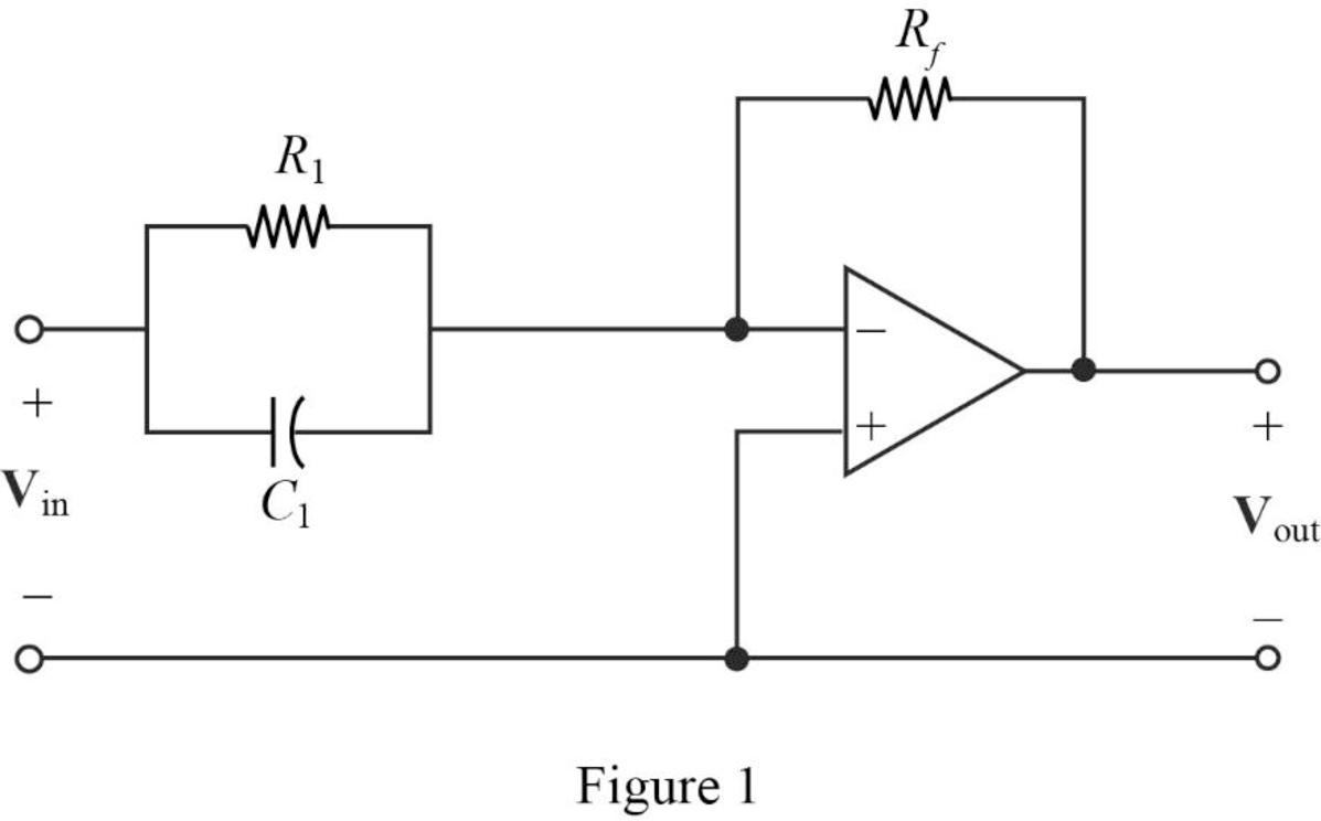
From the Figure 1, a single zero can be written as,
Substitute
Consider the value of
Substitute
Transfer function:
The input impedance of the cascaded circuit in Figure 1 is,
Then, write the Formula for the transfer function for the cascaded two stage amplifier.
Substitute
Thus, consider that the transfer function for
Substitute 50 for
Completing the design by letting
Thus, the final design of the circuit is,
For denominator:
From the transfer function shown in equation (2), it has two repeated poles at
The Figure 14.39 (a) in the textbook, that shows a cascade two stages of the circuit with pole at
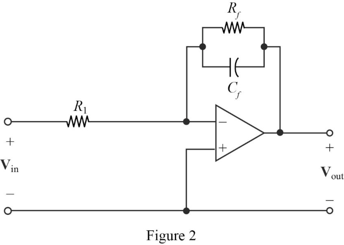
Consider that the cascaded circuit for the two poles representation as shown in Figure 2.
From Figure 2, and the denominator of given transfer function a first pole at
Where, the circuit parameters are considered as
Substitute
Let arbitrarily consider
Substitute 13.3 for
Transfer Function:
Find the feedback impedance of the cascaded circuit in Figure 2.
Write the formula for the transfer function of the cascaded circuit in Figure 2 as follows
Substitute
Therefore, consider the transfer function
Substitute 75 for
Completing the design by letting
Since, two repeated poles are at same
Therefore, the complete transfer function for the denominator part is,
Substitute
Thus, the final design of the two stages cascaded circuit for the denominator part is,
Thus, the overall transfer function of the complete circuit using the transfer function of numerator
Substitute
The input will be inverted, and adding an inverting amplifier with gain of 1 to provide the transfer function as follows.
Conclusion:
Thus, a circuit is designed which produces a transfer function of
Want to see more full solutions like this?
Chapter 14 Solutions
Loose Leaf for Engineering Circuit Analysis Format: Loose-leaf
Additional Engineering Textbook Solutions
Starting Out with Programming Logic and Design (5th Edition) (What's New in Computer Science)
Database Concepts (8th Edition)
Electric Circuits. (11th Edition)
Thermodynamics: An Engineering Approach
Modern Database Management
Mechanics of Materials (10th Edition)


- 7. Complete the following problems for the circuit below. (a) When VDD = 120V, What is the voltage drop V1 across the 7Ω resistor? (b) If the voltage source VDD is set to obtain I1 = 2A, find the value of VDD. (c) If I1 = 100A, What is the value of I2arrow_forwarda) In terms of n and p, how many state variables and how many inputs can you see in the system below? dx1 =x12x2 + 9u1 dt dx2 =x1+x3+3u2 dt dx3 = 4x1 +5x2 - 12x3 dt b) Derive the state space representation for the above system c) Determine whether the system is stable or not.arrow_forwardCircuit Logic. Match each statement to the proper circuit. All circuits have been drawn with a light (L) to represent the load, whether it is a motor, bell, light, or any other load. In addition, each switch is illustrated as a pushbutton whether it is a maintained switch, momentary contact switch, pushbutton, switch-on target, or any other type of switch.arrow_forward
- a) In terms of n and p, how many state variables and how many inputs can you see in the system below? dx1 = 4x1 = x2 dt dx2 =-3x12x2 +U1 dt b) Derive the state space representation for the above system c) Determine whether the system is stable or not.arrow_forwardmatch each statement to the proper circuit. All circuits have been drawn with a light (L) to represent the load, whether it is a motor, bell, light or any other load. In addition, each switch is illustrated as a push button whether it is maintained switch, momentary contact switch, pushbutton, switch-on target, or any other type of switch.arrow_forwarda) In terms of n and p, how many state variables and how many inputs can you see in the system below? dx1 =-7x1 + x2 + 5u1 dt dx2 =-11x1+x3 + 2u1 dt dx3 = -8x16u1 dt b) Derive the state space representation for the above system c) Determine whether the system is stable or not.arrow_forward
- Question 2 (20 points) a) In terms of n and p, how many state variables and how many inputs can you see in the system below? dx1 dt =x1- 2x2 dx2 = 3x1 - 4x2 dt b) Derive the state space representation for the above system c) Determine whether the system is stable or not.arrow_forwardStuck on the question. Please do not use AI, it will get the answer wrong.arrow_forwardConsider a particle confined in an infinite potential well as shown below and its wave function Solve the following problems. is derived as √(x) = A sin (TA), and energy E= H U 0 U=0 a x πλη 2ma² €30 (iii) Calculate the value of A. [Hint: The probability of finding the particle in 0arrow_forwardQ2: Using D flip-flops, design a synchronous counter. The counter counts in the sequence 1,3,5,7, 1,7,5,3,1,3,5,7,.... when its enable input x is equal to 1; otherwise, the counter count 0.arrow_forward8.19 In the circuit shown in Fig. P8.19, u(t) = 40cos(105t) V,R1 = 100 W, R2 = 500 W, C = 0.1 μF, and L = 0.5 mH.Determine the complex power for each passive element, and verifythat conservation of energy is satisfied.arrow_forwardIn the circuit shown, let R₁=7, R₂=12, R3=24, R4-2, V₁ =26, V2=104, and V3-78, to calculate the power delivered (or absorbed) by the circuit inside the box, as follows: {NOTE: On Multiple Choice Questions, like this problem, you have only one attempt } 1. The current I is equal to (choose the closed values in amperes) O 1.156 -1.156 -1.209 -4.622 1.209 0 (A) 4.622 2. The power delivered (or absorbed) (choose the closest value in watts) (W) -873.292 152.225 O 873.292 -122.181 -58.086 0 O 122.181 R₁ ww V₂ R₂ R3 V1 ww R4 √3arrow_forwardarrow_back_iosSEE MORE QUESTIONSarrow_forward_ios
 Introductory Circuit Analysis (13th Edition)Electrical EngineeringISBN:9780133923605Author:Robert L. BoylestadPublisher:PEARSON
 Delmar's Standard Textbook Of ElectricityElectrical EngineeringISBN:9781337900348Author:Stephen L. HermanPublisher:Cengage Learning
 Programmable Logic ControllersElectrical EngineeringISBN:9780073373843Author:Frank D. PetruzellaPublisher:McGraw-Hill Education
 Fundamentals of Electric CircuitsElectrical EngineeringISBN:9780078028229Author:Charles K Alexander, Matthew SadikuPublisher:McGraw-Hill Education
 Electric Circuits. (11th Edition)Electrical EngineeringISBN:9780134746968Author:James W. Nilsson, Susan RiedelPublisher:PEARSON
 Engineering ElectromagneticsElectrical EngineeringISBN:9780078028151Author:Hayt, William H. (william Hart), Jr, BUCK, John A.Publisher:Mcgraw-hill Education,