
Videos
(a)
Design a circuit which produces a transfer function of
(a)
Explanation of Solution
Problem design:
Synthesize a circuit that will yield the transfer function
Calculation:
The transfer function of the circuit is,
The above equation is written as,
For the above transfer function, it has two repeated zeros at
The Figure 14.39 (b) in the textbook, that shows a cascade two stages of the circuit with a zero at
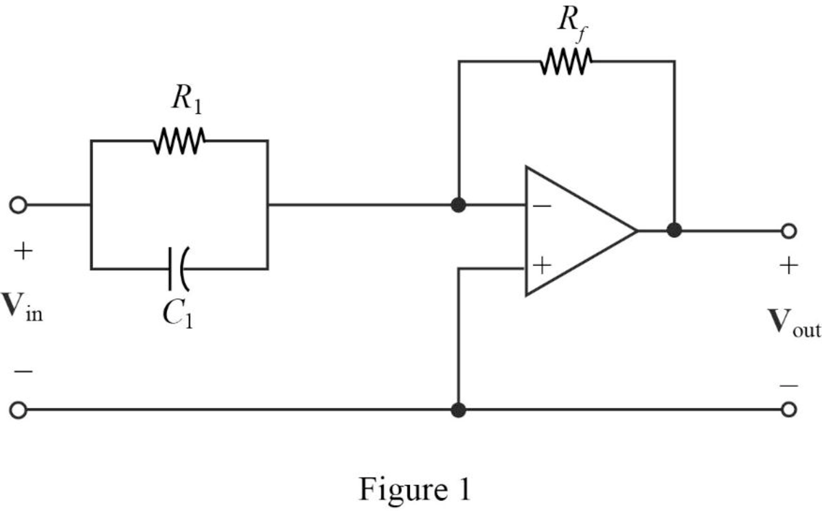
For a single zero,
Substitute
Let arbitrarily consider
Substitute
Transfer function:
The input impedance of the cascaded circuit is,
Then, write the Formula for the transfer function for the cascaded two stage amplifier.
Substitute
Thus, consider that the transfer function for
Substitute 1 for
Completing the design by letting
Since, two repeated zeros at
Therefore,
Substitute
Thus, the final design of the circuit is,
Conclusion:
Thus, a circuit is designed which produces a transfer function of
(b)
Design a circuit which produces a transfer function of
(b)
Explanation of Solution
Problem design:
Synthesize a circuit that will yield the transfer function
Calculation:
The transfer function of the circuit is,
Consider the transfer function for the cascaded circuit as below.
The above transfer function, it has two poles at
The Figure 14.39 (a) in the textbook, that shows a cascade two stages of the circuit with pole at
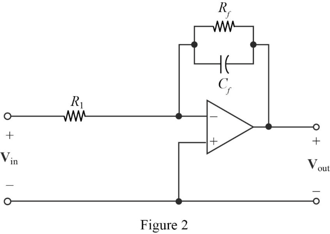
The above Figure 2, is the representation for the first stage and second stage of a cascaded circuit to be drawn.
Consider the denominator of given transfer function and the first pole as
Where,
Substitute
Let arbitrarily consider
Substitute
Transfer function:
Find the feedback impedance of the cascaded circuit in Figure 2.
Write the formula for the transfer function of the cascaded circuit in Figure 2 as follows
Substitute
Therefore, consider the transfer function for the first pole
Substitute 500 for
Completing the design by letting
Consider the denominator of given transfer function and the first pole as
Where,
Substitute
Arbitrarily consider
Substitute
Therefore, consider the transfer function for the second pole
Substitute 100 for
Completing the design by letting
Then, from the transfer function of the two stages write the complete transfer function as follows.
Substitute
Thus, the final design of the circuit is,
Conclusion:
Thus, a circuit is designed which produces a transfer function of
Want to see more full solutions like this?
Chapter 14 Solutions
Loose Leaf for Engineering Circuit Analysis Format: Loose-leaf


- P7.2 The capacitors in the circuit shown below have no energy stored in them and then switch "A" closes at time t=0. Switch "B" closes 2.5 milliseconds later. Find v(t) across the 6 μF capacitor for t≥ 0. 500 Ω B 4 µF 20 V 6 µF 7 Σ2 ΚΩ 25 mA + · μεarrow_forwardQ1: If x[n] is a discrete signal and represented by the following equation, what is the value of x[0] and X[-2] Q2: {x[n]}={-0.2,2.2,1.1,0.2,-3.7,2.9,...} a- Assuming that a 5-bit ADC channel accepts analog input ranging from 0 to 4 volts, determine the following: 1- number of quantization levels; 2-step size of the quantizer or resolution; 3- quantization level when the analog voltage is 1.28 volts. 4- binary code produced by the ADC. 5- quantization error. b- Determine whether the linear system is time invariant or not? 1 1 y(n) = x(n) Q3: Evaluate the digital convolution of the following signals using Graphical method. Find: y(0) to y(3) Q4: 2, k = 0,1,2 2, k = 0 h(k) 0 1, k = 3,4 and x(k) elsewhere = 1, k = 1,2 0 elsewhere The temperature (in Kelvin) of an electronic component can be modelled using the following approximation: T(t) [293+15e-Ju(t) A digital thermometer is used to periodically record the component's temperature, taking a sample every 5 seconds. 1- Represent the…arrow_forwardI need solution by hand clearlyarrow_forward
- fin D Q Point 7.57 in Matlab Aarrow_forwardFor the following graphical figure, write the function x(n) and h(n) in: 1. sequential vector 2. functional representation 3. Tabular 2 h0) 32 If signal x(n)-(32130 104032)], describe this signal using: 1. Graphical representation 2. Tabular representation 3. Write its expression 4. Write it as equation 5. Draw it as y(n) - x(n) u(n-3) 6. Sketch it if it is bounded at -2arrow_forwardFor the following Split-phase Manchester waveform, extract the original binary data. Then draw the AMI code for that data. 0arrow_forward1 ΚΩ N₁ m ZL (10+j4) ks2 178/0° V N2 -202 Ω Figure P11.31 Circuit for Problem 11.31.arrow_forwardCari induktasi saluran transmisi terhadapku GMDarrow_forwardA wattmeter is connected with the positive lead on phase “a” of a three-phase system. The negative lead is connected to phase “b”. A separate wattmeter has the positive lead connected to phase “c”. The negative lead of this wattmeter is connected also to phase “b”. If the input voltage is 208 volts line-to-line, the phase sequence is “abc” and the load is 1200 ohm resistors connected in “Y”, what is the expected reading of each of the wattmeters? (Hint: draw a phasor diagram)arrow_forwardarrow_back_iosSEE MORE QUESTIONSarrow_forward_ios
 Introductory Circuit Analysis (13th Edition)Electrical EngineeringISBN:9780133923605Author:Robert L. BoylestadPublisher:PEARSON
 Delmar's Standard Textbook Of ElectricityElectrical EngineeringISBN:9781337900348Author:Stephen L. HermanPublisher:Cengage Learning
 Programmable Logic ControllersElectrical EngineeringISBN:9780073373843Author:Frank D. PetruzellaPublisher:McGraw-Hill Education
 Fundamentals of Electric CircuitsElectrical EngineeringISBN:9780078028229Author:Charles K Alexander, Matthew SadikuPublisher:McGraw-Hill Education
 Electric Circuits. (11th Edition)Electrical EngineeringISBN:9780134746968Author:James W. Nilsson, Susan RiedelPublisher:PEARSON
 Engineering ElectromagneticsElectrical EngineeringISBN:9780078028151Author:Hayt, William H. (william Hart), Jr, BUCK, John A.Publisher:Mcgraw-hill Education,