
Loose Leaf for Engineering Circuit Analysis Format: Loose-leaf
9th Edition
ISBN: 9781259989452
Author: Hayt
Publisher: Mcgraw Hill Publishers
expand_more
expand_more
format_list_bulleted
Videos
Textbook Question
Chapter 14, Problem 72E
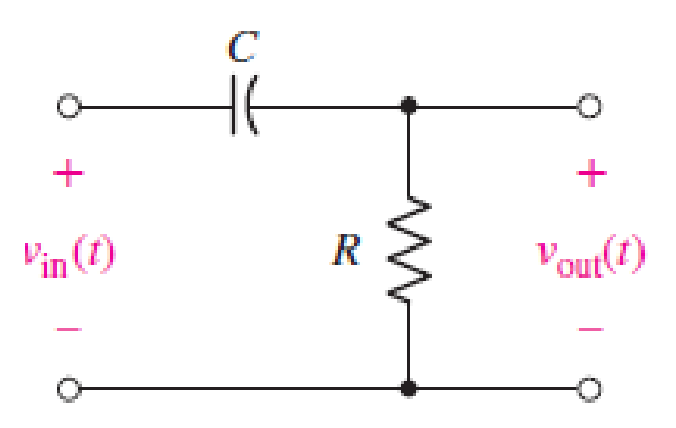
For the network represented schematically in Fig. 14.65, (a) write the transfer function H(s) ≡ Vout(s)/Vin(s); (b) determine the poles and zeros of H(s).
Expert Solution & Answer
Want to see the full answer?
Check out a sample textbook solution
Students have asked these similar questions
Pls show neat and whole solution
Pls show neat and whole solution
Need handwritten solution not using chatgpt Or AI
Chapter 14 Solutions
Loose Leaf for Engineering Circuit Analysis Format: Loose-leaf
Ch. 14.1 - Identify all the complex frequencies present in...Ch. 14.1 - Use real constants A, B, C, , and so forth, to...Ch. 14.2 - Let f (t) = 6e2t [u(t + 3) u(t 2)]. Find the (a)...Ch. 14.3 - Prob. 4PCh. 14.3 - Prob. 5PCh. 14.4 - Prob. 6PCh. 14.4 - Prob. 7PCh. 14.4 - Prob. 8PCh. 14.4 - Prob. 9PCh. 14.5 - Prob. 10P
Ch. 14.5 - Prob. 11PCh. 14.5 - Prob. 12PCh. 14.6 - Prob. 13PCh. 14.7 - Prob. 14PCh. 14.7 - Prob. 15PCh. 14.8 - Find the mesh currents i1 and i2 in the circuit of...Ch. 14.8 - Prob. 17PCh. 14.8 - Prob. 18PCh. 14.9 - Using the method of source transformation, reduce...Ch. 14.9 - Prob. 20PCh. 14.10 - The parallel combination of 0.25 mH and 5 is in...Ch. 14.11 - Prob. 22PCh. 14.11 - Prob. 23PCh. 14.11 - Prob. 24PCh. 14.11 - Prob. 25PCh. 14.12 - Prob. 26PCh. 14 - Determine the conjugate of each of the following:...Ch. 14 - Compute the complex conjugate of each of the...Ch. 14 - Several real voltages are written down on a piece...Ch. 14 - State the complex frequency or frequencies...Ch. 14 - For each of the following functions, determine the...Ch. 14 - Use real constants A, B, , , etc. to construct the...Ch. 14 - The following voltage sources AeBt cos(Ct + ) are...Ch. 14 - Prob. 8ECh. 14 - Compute the real part of each of the following...Ch. 14 - Your new assistant has measured the signal coming...Ch. 14 - Prob. 11ECh. 14 - Prob. 12ECh. 14 - Prob. 13ECh. 14 - Prob. 14ECh. 14 - Prob. 15ECh. 14 - Prob. 16ECh. 14 - Determine F(s) if f (t) is equal to (a) 3u(t 2);...Ch. 14 - Prob. 18ECh. 14 - Prob. 19ECh. 14 - Prob. 20ECh. 14 - Prob. 21ECh. 14 - Evaluate the following: (a)[(2t)]2 at t = 1;...Ch. 14 - Evaluate the following expressions at t = 0: (a)...Ch. 14 - Prob. 24ECh. 14 - Prob. 25ECh. 14 - Prob. 26ECh. 14 - Prob. 27ECh. 14 - Prob. 28ECh. 14 - Prob. 29ECh. 14 - Prob. 30ECh. 14 - Prob. 31ECh. 14 - Prob. 32ECh. 14 - Prob. 33ECh. 14 - Obtain the time-domain expression which...Ch. 14 - Prob. 35ECh. 14 - Prob. 36ECh. 14 - Prob. 37ECh. 14 - Prob. 38ECh. 14 - Prob. 39ECh. 14 - Prob. 40ECh. 14 - Prob. 41ECh. 14 - Obtain, through purely legitimate means, an...Ch. 14 - Prob. 43ECh. 14 - Employ the initial-value theorem to determine the...Ch. 14 - Prob. 45ECh. 14 - Prob. 46ECh. 14 - Prob. 47ECh. 14 - Prob. 48ECh. 14 - Prob. 49ECh. 14 - Prob. 52ECh. 14 - Determine v(t) for t 0 for the circuit shown in...Ch. 14 - Prob. 54ECh. 14 - Prob. 55ECh. 14 - For the circuit of Fig. 14.54, (a) draw both...Ch. 14 - Prob. 58ECh. 14 - Prob. 59ECh. 14 - Prob. 60ECh. 14 - For the circuit shown in Fig. 14.58, let is1 =...Ch. 14 - Prob. 63ECh. 14 - Prob. 64ECh. 14 - For the circuit shown in Fig. 14.62, determine the...Ch. 14 - Prob. 67ECh. 14 - Prob. 68ECh. 14 - Determine the poles and zeros of the following...Ch. 14 - Use appropriate means to ascertain the poles and...Ch. 14 - Prob. 71ECh. 14 - For the network represented schematically in Fig....Ch. 14 - Prob. 73ECh. 14 - Prob. 74ECh. 14 - Prob. 75ECh. 14 - Prob. 76ECh. 14 - Prob. 77ECh. 14 - Prob. 78ECh. 14 - Prob. 79ECh. 14 - Prob. 80ECh. 14 - Prob. 81ECh. 14 - Prob. 82ECh. 14 - Design a circuit which produces the transfer...Ch. 14 - Prob. 84ECh. 14 - Prob. 85ECh. 14 - An easy way to get somebodys attention is to use a...Ch. 14 - Prob. 87E
Knowledge Booster


Learn more about
Need a deep-dive on the concept behind this application? Look no further. Learn more about this topic, electrical-engineering and related others by exploring similar questions and additional content below.Similar questions
- 1) A circuit is given as shown. (a) Find and label the circuit nodes. (6) Determine I, II, I₂ and V, I mm 22 +1 m 50 4 12 12v 2 ти + V ≤1652 50 mv Ми 60arrow_forwardHANDWRITTEN SOLUTION NOT USING CHATGPT PLEASEarrow_forwardDesign a full-wave rectifier power supply using a 9.52:1 transformer. Assume that the outlet is120 V rms @ 60 Hz. Further assume that the diode turn-on voltage V D(on) is 0.7 V. Pick the valueof CL such that vo has a maximum ripple of 1 V p-p . Solve for the average value of vo = Vo (notethat this may be greater than 12 V) and iD(ave) = ID.arrow_forward
- Light-emitting diodes (LEDs) are diodes made with III-V compound semiconductor materials such as aluminum gallium arsenide (AlGaAs), aluminum indium gallium phosphide (AlInGaP) or indium gallium nitride (InGaN), instead of silicon. The LEDs emit light when the device is operated under forward bias. LEDs of different colors have different turn-on voltages VD(on). For example: VD(on) : Red: ~ 1.6 V Yellow: ~ 1.7 V Green: ~ 1.8 V Blue: ~ 2.8 V White: ~ 3.8 V (a) Model these five LEDs with a simplified piecewise linear model (b) A rule of thumb is that it takes about 1 mA of current to “light” an LED while ~ 10 mA is needed for it to appear bright. Use the piecewise linear model for the LEDs, for the over-voltage indicator circuit to the right, find the values of Vin which will cause D1 or D2 to light (i.e. when ID1 or ID2 exceeds 1 mA).arrow_forwardConsider a fixed and updated instrumentation amplifier (where two resistors are lumped into one resistor), analyze the circuit if a common voltage source (VICM) is connected to two inputs. A₁ R₂ + R₁ R₂, RA www www R₁ R₁ www A3 X R₁ R₂ www www R₁₂ + Vo RA A2 V2 O- + R₂ 12 R₁arrow_forwardShow that the input impedance of a lossy transmission line of length L connected to a load impedance of Z is given by Z₁Cosh(yL) + ZoSinh(yL) Zin = Zo ZoCosh(YL) + Z₁Sihh(YL) ex Where Cosh(x) = and Sinh(x) = are the hyperbolic cosine and sine, respectively. 2 2arrow_forward
- A sinusoidal source of V = 10 and Z = 50 - j40 is connected to a 60 lossless transmission line of length 100 m with ẞ = 0.25. What is the Thevenin's equivalent of this system seen looking into the load end of the transmission line?arrow_forward2. On a distortionless transmission line, the voltage wave is given by v(L,t) = 110e0.005L Cos(10³t + 2L) +55e-0.005L Cos(108t-2L) where L is the length of the transmission line as measured from the load. If Z = 30002, find a,ẞ, vp, and Zo.arrow_forwardA 50 transmission line is to be connected to a 72 load through a 1/4 quarter wave matching transformer. (a) What must be the characteristic impedance of the transmission line that is used to form the quarter wave transformer? (b) If the frequency of operation is 7 MHz and the phase velocity through the quarter wave section is 2c/3, what is the length of the quarter wave section? You may assume the transmission line forming the quarter wave section is lossless.arrow_forward
arrow_back_ios
SEE MORE QUESTIONS
arrow_forward_ios
Recommended textbooks for you
 Introductory Circuit Analysis (13th Edition)Electrical EngineeringISBN:9780133923605Author:Robert L. BoylestadPublisher:PEARSON
 Delmar's Standard Textbook Of ElectricityElectrical EngineeringISBN:9781337900348Author:Stephen L. HermanPublisher:Cengage Learning
 Programmable Logic ControllersElectrical EngineeringISBN:9780073373843Author:Frank D. PetruzellaPublisher:McGraw-Hill Education
 Fundamentals of Electric CircuitsElectrical EngineeringISBN:9780078028229Author:Charles K Alexander, Matthew SadikuPublisher:McGraw-Hill Education
 Electric Circuits. (11th Edition)Electrical EngineeringISBN:9780134746968Author:James W. Nilsson, Susan RiedelPublisher:PEARSON
 Engineering ElectromagneticsElectrical EngineeringISBN:9780078028151Author:Hayt, William H. (william Hart), Jr, BUCK, John A.Publisher:Mcgraw-hill Education,
Introductory Circuit Analysis (13th Edition)
Electrical Engineering
ISBN:9780133923605
Author:Robert L. Boylestad
Publisher:PEARSON
Delmar's Standard Textbook Of Electricity
Electrical Engineering
ISBN:9781337900348
Author:Stephen L. Herman
Publisher:Cengage Learning
Programmable Logic Controllers
Electrical Engineering
ISBN:9780073373843
Author:Frank D. Petruzella
Publisher:McGraw-Hill Education
Fundamentals of Electric Circuits
Electrical Engineering
ISBN:9780078028229
Author:Charles K Alexander, Matthew Sadiku
Publisher:McGraw-Hill Education
Electric Circuits. (11th Edition)
Electrical Engineering
ISBN:9780134746968
Author:James W. Nilsson, Susan Riedel
Publisher:PEARSON
Engineering Electromagnetics
Electrical Engineering
ISBN:9780078028151
Author:Hayt, William H. (william Hart), Jr, BUCK, John A.
Publisher:Mcgraw-hill Education,
Nyquist 1 - what is a Nyquist diagram?; Author: John Rossiter;https://www.youtube.com/watch?v=mgIvOk9JGKY;License: Standard Youtube License