
Concept explainers
Videos
(a)
The value of
(a)
Answer to Problem 63E
The voltage
Explanation of Solution
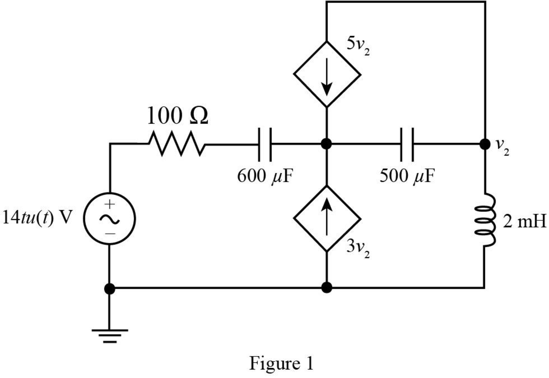
Given data:
The resistive component of the circuit is of
The capacitive components of the circuit are
The values of voltage dependent current sources are
The inductive component of the circuit is of
The input voltage of the circuit is
The time
The given diagram is shown in Figure 1.
Calculation:
Let the resistance
The conversion of
The conversion of
The conversion of
The conversion from
The conversion from
The voltage source
The Laplace transform of capacitance is given by,
The Laplace transform of
The Laplace transform of
The Laplace transform of inductor is given by,
The Laplace transform of
Mark the nodes apply mesh analysis to the circuit and redraw the circuit in
The required diagram is shown in Figure 2.
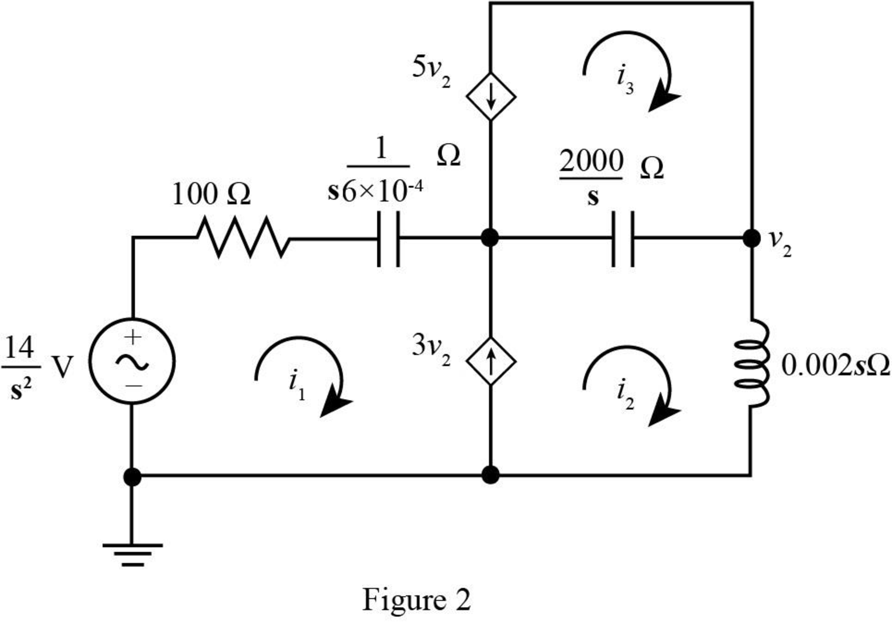
The output voltage
The value of node voltage
The current source
The super mesh equation is given as,
Substitute
The current flowing through the loop 3 is given by,
Substitute
Apply Kirchhoff’s voltage law at the super mesh.
Substitute
Solve further as,
Substitute
The above equation in partial form is written as,
Substitute
Substitute
Substitute
Substitute
Apply inverse Laplace transform to the above equation.
7
The conversion from
The conversion of
Substitute
Conclusion:
Therefore he value of
(b)
The value of
(b)
Answer to Problem 63E
The voltage
Explanation of Solution
Given data:
The value of
Calculation:
The conversion from
The conversion of
Substitute
Conclusion:
Thus, the voltage
(c)
The value of
(c)
Answer to Problem 63E
The voltage
Explanation of Solution
Given data:
The value of
Calculation:
Substitute
Conclusion:
Thus, the voltage
Want to see more full solutions like this?
Chapter 14 Solutions
Loose Leaf for Engineering Circuit Analysis Format: Loose-leaf


- engineering electromagnetics subjectarrow_forwardD8.2. The field B = -2ax + 3ay + 4a, mT is present in free space. Find the vector force exerted on a straight wire carrying 12 A in the aAB direction, given A(1, 1, 1) and: (a) B(2, 1, 1); (b) B(3, 5, 6). Ans. -48ay +36a, mN; 12ax - 216ay + 168az mNarrow_forward3 In a certain medium If μ = - E = 10 cos (2 x 10't ẞx)(a, + a.) V/m 50μo, ε = 28, and σ 0, find ẞ and H.arrow_forward
- A plane wave propagating through a medium with &,,-8 μr = 2 nas: E = 0.5 e-j0.33z sin (108 t - Bz) ax V/m. Determine (a) ẞ (b) The loss tangent (c) Wave impedance (d) Wave velocity (e) H fieldarrow_forwardIn a medium, E = 16e 0.05x sin (2 x 10²x) a₂ V/m find: (a) the propagation constant, (b) the wavelength, (c) the speed of the wave, (d) the skin depth.arrow_forwardengineering electromagnetics subjectarrow_forward
- In a homogenous media for which ε = 49, μr = 1 the Electric field intensity and the magnetic lux density are E = 20π cos(wt - Bz) ax, B = Ho Ho cos(wt-ẞz) ay respectively, and λ = 1.8m. Determine the type of media, the value of Ho, w and the direction of propagation?arrow_forwardA plane wave propagating through a medium with ɛ, = ez/3 sin(108 - Bz)ax V/m. Determine (a) B (b) The loss tangent (c) Intrinsic impedance (d) Wave velocity (e) H field = 8, μ, 2 hasarrow_forward1. Consider the systems whose transfer functions are given as below. Determine (i) BIBO stability, (ii) strict internal stability, and (iii) marginally internal stability for each of the systems. You should be able to answer these just simply finding the poles and checking sign of real part of the poles. a) H(s) = (s-3) (s+1) (s+3)² 2 (s-5) b) H(s) = c) H(s) = (s-5)(s+1) $2 ((s+3)²+4)2 d) H(s) = e) H(s) = S (s-3)²+4 (S-4) (s²-4s)(s+1)² f) H(s) = S+1 (s²+9)2arrow_forward
 Introductory Circuit Analysis (13th Edition)Electrical EngineeringISBN:9780133923605Author:Robert L. BoylestadPublisher:PEARSON
 Delmar's Standard Textbook Of ElectricityElectrical EngineeringISBN:9781337900348Author:Stephen L. HermanPublisher:Cengage Learning
 Programmable Logic ControllersElectrical EngineeringISBN:9780073373843Author:Frank D. PetruzellaPublisher:McGraw-Hill Education
 Fundamentals of Electric CircuitsElectrical EngineeringISBN:9780078028229Author:Charles K Alexander, Matthew SadikuPublisher:McGraw-Hill Education
 Electric Circuits. (11th Edition)Electrical EngineeringISBN:9780134746968Author:James W. Nilsson, Susan RiedelPublisher:PEARSON
 Engineering ElectromagneticsElectrical EngineeringISBN:9780078028151Author:Hayt, William H. (william Hart), Jr, BUCK, John A.Publisher:Mcgraw-hill Education,