
Mechanics of Materials, 7th Edition
7th Edition
ISBN: 9780073398235
Author: Ferdinand P. Beer, E. Russell Johnston Jr., John T. DeWolf, David F. Mazurek
Publisher: McGraw-Hill Education
expand_more
expand_more
format_list_bulleted
Concept explainers
Videos
Textbook Question
Chapter 1.2, Problem 11P
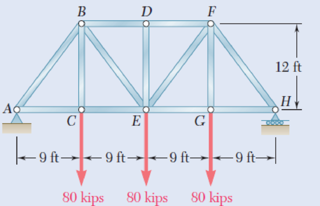
For the Pratt bridge truss and loading shown, determine the average normal stress in member BE, knowing that the cross-sectional area of that member is 5.87 in2.
Fig. P1.11
Expert Solution & Answer
Want to see the full answer?
Check out a sample textbook solution
Students have asked these similar questions
Pearson eText
Study Area
Document Sharing
User Settings
mylabmastering.pearson.com
Access Pearson
P Pearson MyLab and Mastering
Problem 15.96
Part A
In (Figure 1), take m₁ = 3.4 kg and m =
4.8 kg.
Figure
1 of 1
P Course Home
b Answered: HW_02.pdf EE 213-01 > Assignments HW_#...
7 of 8
Determine the component of the angular momentum Ho of particle A about point O.
Express your answer in kilogram-meters squared per second to three significant figures.
(Ho) z
=
-ΜΕ ΑΣΦ
vec
Submit
Request Answer
Part B
?
kg m2/s
Determine the component of the angular momentum Ho of particle B about point O. Suppose that
Express your answer in kilogram-meters squared per second to three significant figures.
ΜΕ ΑΣΦ
vec
Symbols
(Ho)z =
Submit
Request Answer
Provide Feedback
?
kg m2/s
Review
Next >
Pearson eText
Study Area
Document Sharing
User Settings
mylabmastering.pearson.com
Access Pearson
P Pearson MyLab and Mastering
Problem 14.69
Part A
P Course Home
b Answered: HW_02.pdf EE 213-01 > Assignments HW_#...
1 of 8
Review
The 5-kg collar has a velocity of 7 m/s to the right when
it is at A. It then travels down along the smooth guide
shown in (Figure 1). The spring has an unstretched
length of 100 mm and B is located just before the end
of the curved portion of the rod.
Determine the speed of the collar when it reaches point B, which is located just before the end of the curved portion of the rod.
Express your answer to three significant figures and include the appropriate units.
Figure
1 of 1
με
v =
Value
Units
Submit
Request Answer
Part B
?
What is the normal force on the collar at this instant?
Express your answer to three significant figures and include the appropriate units.
☐
μÅ
?
N =
Value
Units
Submit
Request Answer
Provide Feedback
Next >
Pearson eText
Study Area
mylabmastering.pearson.com
Access Pearson
P Pearson MyLab and Mastering
Problem 15.106
P Course Home
b Answered: HW_02.pdf EE 213-01 > Assignments HW_#...
8 of 8
Document Sharing
User Settings
The two spheres A and B each have a mass of 400 g.
The spheres are fixed to the horizontal rods as shown in
(Figure 1) and their initial velocity is 2 m/s. The mass of
the supporting frame is negligible and it is free to rotate.
Neglect the size of the spheres.
Part A
If a couple moment of M = 0.3 N · m is applied to the frame, determine the speed of the spheres in 3 s.
Express your answer to three significant figures and include the appropriate units.
Figure
1 of 1
☐
?
v =
Value
Units
Units input for part A
Submit
Request Answer
Return to Assignment
Provide Feedback
■Review
Chapter 1 Solutions
Mechanics of Materials, 7th Edition
Ch. 1.2 - Two solid cylindrical rods AB and BC are welded...Ch. 1.2 - Two solid cylindrical rods AB and BC are welded...Ch. 1.2 - Two solid cylindrical rods AB and BC are welded...Ch. 1.2 - Two solid cylindrical rods AB and BC are welded...Ch. 1.2 - A strain gage located at C on the surface of bone...Ch. 1.2 - Two brass rods AB and BC, each of uniform...Ch. 1.2 - Each of the four vertical links has an 8 36-mm...Ch. 1.2 - Link AC has a uniform rectangular cross section 18...Ch. 1.2 - Three forces, each of magnitude P = 4 kN, are...Ch. 1.2 - Link BD consists of a single bar 1 in. wide and 12...
Ch. 1.2 - For the Pratt bridge truss and loading shown,...Ch. 1.2 - The frame shown consists of four wooden members,...Ch. 1.2 - An aircraft tow bar is positioned by means of a...Ch. 1.2 - Two hydraulic cylinders are used to control the...Ch. 1.2 - Determine the diameter of the largest circular...Ch. 1.2 - Two wooden planks, each 12 in. thick and 9 in....Ch. 1.2 - When the force P reached 1600 lb, the wooden...Ch. 1.2 - A load P is applied to a steel rod supported as...Ch. 1.2 - The axial force in the column supporting the...Ch. 1.2 - Three wooden planks are fastened together by a...Ch. 1.2 - A 40-kN axial load is applied to a short wooden...Ch. 1.2 - An axial load P is supported by a short W8 40...Ch. 1.2 - Link AB, of width b = 2 in. and thickness t=14...Ch. 1.2 - Determine the largest load P that can be applied...Ch. 1.2 - Knowing that = 40 and P = 9 kN, determine (a) the...Ch. 1.2 - The hydraulic cylinder CF, which partially...Ch. 1.2 - For the assembly and loading of Prob. 1.7,...Ch. 1.2 - Two identical linkage-and-hydraulic-cylinder...Ch. 1.5 - Two wooden members of uniform rectangular cross...Ch. 1.5 - Two wooden members of uniform rectangular cross...Ch. 1.5 - The 1.4-kip load P is supported by two wooden...Ch. 1.5 - Two wooden members of uniform cross section are...Ch. 1.5 - A centric load P is applied to the granite block...Ch. 1.5 - A 240-kip load P is applied to the granite block...Ch. 1.5 - A steel pipe of 400-mm outer diameter is...Ch. 1.5 - A steel pipe of 400-mm outer diameter is...Ch. 1.5 - A steel loop ABCD of length 5 ft and of 38-in....Ch. 1.5 - Link BC is 6 mm thick, has a width w = 25 mm, and...Ch. 1.5 - Link BC is 6 mm thick and is made of a steel with...Ch. 1.5 - Members AB and BC of the truss shown are made of...Ch. 1.5 - Members AB and BC of the truss shown are made of...Ch. 1.5 - Link AB is to be made of a steel for which the...Ch. 1.5 - Two wooden members are joined by plywood splice...Ch. 1.5 - For the joint and loading of Prob. 1.43, determine...Ch. 1.5 - Three 34-in.-diameter steel bolts are to be used...Ch. 1.5 - Three steel bolts are to be used to attach the...Ch. 1.5 - A load P is supported as shown by a steel pin that...Ch. 1.5 - A load P is supported as shown by a steel pin that...Ch. 1.5 - A steel plate 14 in. thick is embedded in a...Ch. 1.5 - Determine the factor of safety for the cable...Ch. 1.5 - Link AC is made of a steel with a 65-ksi ultimate...Ch. 1.5 - Solve Prob. 1.51, assuming that the structure has...Ch. 1.5 - Each of the two vertical links CF connecting the...Ch. 1.5 - Solve Prob. 1.53, assuming that the pins at C and...Ch. 1.5 - In the structure shown, an 8-mm-diameter pin is...Ch. 1.5 - In an alternative design for the structure of...Ch. 1.5 - Prob. 57PCh. 1.5 - The Load and Resistance Factor Design method is to...Ch. 1 - In the marine crane shown, link CD is known to...Ch. 1 - Two horizontal 5-kip forces are applied to pin B...Ch. 1 - For the assembly and loading of Prob. 1.60,...Ch. 1 - Two steel plates are to be held together by means...Ch. 1 - A couple M of magnitude 1500 N m is applied to...Ch. 1 - Knowing that link DE is 18 in. thick and 1 in....Ch. 1 - A 58-in.-diameter steel rod AB is fitted to a...Ch. 1 - In the steel structure shown, a 6-mm-diameter pin...Ch. 1 - Prob. 67RPCh. 1 - A force P is applied as shown to a steel...Ch. 1 - The two portions of member AB are glued together...Ch. 1 - The two portions of member AB are glued together...
Knowledge Booster


Learn more about
Need a deep-dive on the concept behind this application? Look no further. Learn more about this topic, mechanical-engineering and related others by exploring similar questions and additional content below.Similar questions
- Pearson eText Study Area Access Pearson mylabmastering.pearson.com P Pearson MyLab and Mastering Problem 15.79 P Course Home b Answered: HW_02.pdf EE 213-01 > Assignments HW_#... 6 of 8 > Document Sharing User Settings The two disks A and B have a mass of 4 kg and 5 kg, respectively. They collide with the initial velocities shown. The coefficient of restitution is e = 0.65. Suppose that (VA)1 = 6 m/s, (VB)1 = 8 m/s. (Figure 1) Part A Determine the magnitude of the velocity of A just after impact. Express your answer to three significant figures and include the appropriate units. Figure 1 of 1 μÅ (VA)2 = Value Units Submit Request Answer Part B ? Review Determine the angle between the x axis and the velocity of A just after impact, measured clockwise from the negative x axis. Express your answer in degrees to three significant figures. ΕΠΙ ΑΣΦ vec 01 Submit Request Answer Part C ? Determine the magnitude of the velocity of B just after impact. Express your answer to three significant…arrow_forward40.00 30.00 100.00- 100.00 P = 1000 N A=167 d=140.00 100.00- -b 20.00 200.00 Weld Strength P = 273 N/mm^2 Electrod E60 Safety factor S₁ = 3 Force P = 1000 N Using by SOLIDWORKSarrow_forwardWhat are the reaction forces in A and B?arrow_forward
- Pearson eText Study Area Access Pearson mylabmastering.pearson.com P Pearson MyLab and Mastering Problem 15.6 P Course Home b Answered: HW_02.pdf EE 213-01 > Assignments HW_#... 3 of 8 ■ Review Document Sharing User Settings The jet plane has a mass of 250 Mg and a horizontal velocity of 100 m/s when t = 0. Part A If both engines provide a horizontal thrust which varies as shown in the graph in (Figure 1), determine the plane's velocity in 5 s. Neglect air resistance and the loss of fuel during the motion. Express your answer to three significant figures and include the appropriate units. Figure 1 of 1 > ☐ μÅ ? v = Value Units Submit Request Answer Provide Feedback Next >arrow_forwardAccess Pearson mylabmastering.pearson.com P Pearson MyLab and Mastering Problem 15.43 P Course Home b Answered: HW_02.pdf EE 213-01 > Assignments HW_#... Pearson eText Study Area Document Sharing User Settings The 20-g bullet is travelling at 400 m/s when it becomes embedded in the 2-kg stationary block. The coefficient of kinetic friction between the block and the plane is μk = 0.2. (Figure 1) Part A Determine the distance the block will slide before it stops. Express your answer to three significant figures and include the appropriate units. Figure 1 of 1 με S = Value Units Submit Request Answer Provide Feedback ? 4 of 8 Review Next >arrow_forwardAccess Pearson mylabmastering.pearson.com P Pearson MyLab and Mastering Problem 15.64 P Course Home b Answered: HW_02.pdf EE 213-01 > Assignments HW_#... 5 of 8 Pearson eText Study Area Document Sharing User Settings Ball A has a mass of 3 kg and is moving with a velocity of (VA)1 = 8 m/s when it makes a direct collision with ball B, which has a mass of 2.5 kg and is moving with a velocity of (VB) 1 = 4 m/s. Suppose that e = 0.7. Neglect the size of the balls. (Figure 1) Part A Determine the velocity of A just after the collision. ■Review Express your answer to three significant figures and include the appropriate units. Assume the positive direction is to the right. Figure 1 of 1 ◎ на ? (VA)2= Value Units Submit Request Answer Part B Determine the velocity of B just after the collision. Express your answer to three significant figures and include the appropriate units. Assume the positive direction is to the right. μÅ ? (VB)2= = Value Units Submit Request Answer Provide Feedback Next…arrow_forward
- I only need help with number 3, actually just the theta dot portion. Thanks! I have Vr = 10.39 ft/sarrow_forwardOnly 100% sure experts solve it correct complete solutions okk don't use guidelines or ai answers okk will dislike okkk. Only human experts solved itarrow_forwardAirplanes A and B, flying at constant velocity and at the same altitude, are tracking the eye of hurricane C. The relative velocity of C with respect to A is 300 kph 65.0° South of West, and the relative velocity of C with respect to B is 375 kph 50.0° South of East. A 120.0 km B 1N 1. Determine the relative velocity of B with respect to A. A ground-based radar indicates that hurricane C is moving at a speed of 40.0 kph due north. 2. Determine the velocity of airplane A. 3. Determine the velocity of airplane B. Consider that at the start of the tracking expedition, the distance between the planes is 120.0 km and their initial positions are horizontally collinear. 4. Given the velocities obtained in items 2 and 3, should the pilots of planes A and B be concerned whether the planes will collide at any given time? Prove using pertinent calculations. (Hint: x = x + vt) 0arrow_forward
- Only 100% sure experts solve it correct complete solutions okk don't use guidelines or ai answers okk will dislike okkk.arrow_forwardSolve this probem and show all of the workarrow_forwardThe differential equation of a cruise control system is provided by the following equation: WRITE OUT SOLUTION DO NOT USE A COPIED SOLUTION Find the closed loop transfer function with respect to the reference velocity (vr) . a. Find the poles of the closed loop transfer function for different values of K. How does the poles move as you change K? b. Find the step response for different values of K and plot in MATLAB. What can you observe?arrow_forward
arrow_back_ios
SEE MORE QUESTIONS
arrow_forward_ios
Recommended textbooks for you
 Elements Of ElectromagneticsMechanical EngineeringISBN:9780190698614Author:Sadiku, Matthew N. O.Publisher:Oxford University Press
 Mechanics of Materials (10th Edition)Mechanical EngineeringISBN:9780134319650Author:Russell C. HibbelerPublisher:PEARSON
 Thermodynamics: An Engineering ApproachMechanical EngineeringISBN:9781259822674Author:Yunus A. Cengel Dr., Michael A. BolesPublisher:McGraw-Hill Education
 Control Systems EngineeringMechanical EngineeringISBN:9781118170519Author:Norman S. NisePublisher:WILEY
 Mechanics of Materials (MindTap Course List)Mechanical EngineeringISBN:9781337093347Author:Barry J. Goodno, James M. GerePublisher:Cengage Learning
 Engineering Mechanics: StaticsMechanical EngineeringISBN:9781118807330Author:James L. Meriam, L. G. Kraige, J. N. BoltonPublisher:WILEY
Elements Of Electromagnetics
Mechanical Engineering
ISBN:9780190698614
Author:Sadiku, Matthew N. O.
Publisher:Oxford University Press
Mechanics of Materials (10th Edition)
Mechanical Engineering
ISBN:9780134319650
Author:Russell C. Hibbeler
Publisher:PEARSON
Thermodynamics: An Engineering Approach
Mechanical Engineering
ISBN:9781259822674
Author:Yunus A. Cengel Dr., Michael A. Boles
Publisher:McGraw-Hill Education
Control Systems Engineering
Mechanical Engineering
ISBN:9781118170519
Author:Norman S. Nise
Publisher:WILEY
Mechanics of Materials (MindTap Course List)
Mechanical Engineering
ISBN:9781337093347
Author:Barry J. Goodno, James M. Gere
Publisher:Cengage Learning
Engineering Mechanics: Statics
Mechanical Engineering
ISBN:9781118807330
Author:James L. Meriam, L. G. Kraige, J. N. Bolton
Publisher:WILEY
Engineering Basics - Statics & Forces in Equilibrium; Author: Solid Solutions - Professional Design Solutions;https://www.youtube.com/watch?v=dQBvQ2hJZFg;License: Standard YouTube License, CC-BY