
Mechanics of Materials, 7th Edition
7th Edition
ISBN: 9780073398235
Author: Ferdinand P. Beer, E. Russell Johnston Jr., John T. DeWolf, David F. Mazurek
Publisher: McGraw-Hill Education
expand_more
expand_more
format_list_bulleted
Concept explainers
Videos
Textbook Question
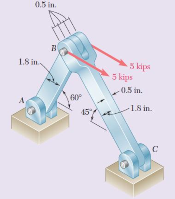
Chapter 1, Problem 60RP
Two horizontal 5-kip forces are applied to pin B of the assembly shown. Knowing that a pin of 0.8-in. diameter is used at each connection, determine the maximum value of the average normal stress (a) in link AB, (b) in link BC.
Fig. P1.60
Expert Solution & Answer
Want to see the full answer?
Check out a sample textbook solution
Students have asked these similar questions
4. Two links made of heat treated 6061 aluminum (Sy = 276 MPa, Sys = 160 MPa) are pinned
together using a steel dowel pin (Sy = 1398 MPa, Sys = 806 MPa) as shown below. The
links are to support a load P with a factor of safety of at least 2.0. Determine if the link will
fail first by tearout, direct shear of the pin, bearing stress on the link, or tensile stress at
section AA. (Hint: find the load P for each case and choose the case that gives the smallest
load.)
P
8 mm
P
8 mm
¡+A
3 mm
→A
10 mm
P
1. For a feature other than a sphere, circularity is where:
A. The axis is a straight line
B. The modifier is specified with a size dimension
C. All points of the surface intersected by any plane
perpendicular to an axis or spine (curved line) are
equidistant from that axis or spine
D. All points of the surface intersected by any plane
passing through a common center are equidistant
from that center
2. What type of variation is limited by a circularity toler-
ance zone?
A. Ovality
B. Tapering
C. Bending
D. Warping
3. How does the Rule #1 boundary affect the application
of a circularity tolerance?
A. The modifier must be used.
B. The feature control frame must be placed next to
the size dimension.
C. The circularity tolerance value must be less than
the limits of size tolerance.
D. Circularity cannot be applied where a Rule #1
boundary exists.
4. A circularity tolerance may use a
modifier.
A. Ø
B. F
C. M
D. ℗
5. A real-world application for a circularity tolerance is:
A. Assembly (i.e.,…
3. A steel bar is pinned to a vertical support column by a 10 mm diameter hardened dowel pin,
Figure 1. For P = 7500 N, find:
a. the shear stress in the pin,
b. the direct bearing stress on the hole in the bar,
c. the minimum value of d to prevent tearout failure if the steel bar has a shear strength of
175 MPa.
support column
pin
bar
thickness of bar = 8 mm
h
d
150 mm
Chapter 1 Solutions
Mechanics of Materials, 7th Edition
Ch. 1.2 - Two solid cylindrical rods AB and BC are welded...Ch. 1.2 - Two solid cylindrical rods AB and BC are welded...Ch. 1.2 - Two solid cylindrical rods AB and BC are welded...Ch. 1.2 - Two solid cylindrical rods AB and BC are welded...Ch. 1.2 - A strain gage located at C on the surface of bone...Ch. 1.2 - Two brass rods AB and BC, each of uniform...Ch. 1.2 - Each of the four vertical links has an 8 36-mm...Ch. 1.2 - Link AC has a uniform rectangular cross section 18...Ch. 1.2 - Three forces, each of magnitude P = 4 kN, are...Ch. 1.2 - Link BD consists of a single bar 1 in. wide and 12...
Ch. 1.2 - For the Pratt bridge truss and loading shown,...Ch. 1.2 - The frame shown consists of four wooden members,...Ch. 1.2 - An aircraft tow bar is positioned by means of a...Ch. 1.2 - Two hydraulic cylinders are used to control the...Ch. 1.2 - Determine the diameter of the largest circular...Ch. 1.2 - Two wooden planks, each 12 in. thick and 9 in....Ch. 1.2 - When the force P reached 1600 lb, the wooden...Ch. 1.2 - A load P is applied to a steel rod supported as...Ch. 1.2 - The axial force in the column supporting the...Ch. 1.2 - Three wooden planks are fastened together by a...Ch. 1.2 - A 40-kN axial load is applied to a short wooden...Ch. 1.2 - An axial load P is supported by a short W8 40...Ch. 1.2 - Link AB, of width b = 2 in. and thickness t=14...Ch. 1.2 - Determine the largest load P that can be applied...Ch. 1.2 - Knowing that = 40 and P = 9 kN, determine (a) the...Ch. 1.2 - The hydraulic cylinder CF, which partially...Ch. 1.2 - For the assembly and loading of Prob. 1.7,...Ch. 1.2 - Two identical linkage-and-hydraulic-cylinder...Ch. 1.5 - Two wooden members of uniform rectangular cross...Ch. 1.5 - Two wooden members of uniform rectangular cross...Ch. 1.5 - The 1.4-kip load P is supported by two wooden...Ch. 1.5 - Two wooden members of uniform cross section are...Ch. 1.5 - A centric load P is applied to the granite block...Ch. 1.5 - A 240-kip load P is applied to the granite block...Ch. 1.5 - A steel pipe of 400-mm outer diameter is...Ch. 1.5 - A steel pipe of 400-mm outer diameter is...Ch. 1.5 - A steel loop ABCD of length 5 ft and of 38-in....Ch. 1.5 - Link BC is 6 mm thick, has a width w = 25 mm, and...Ch. 1.5 - Link BC is 6 mm thick and is made of a steel with...Ch. 1.5 - Members AB and BC of the truss shown are made of...Ch. 1.5 - Members AB and BC of the truss shown are made of...Ch. 1.5 - Link AB is to be made of a steel for which the...Ch. 1.5 - Two wooden members are joined by plywood splice...Ch. 1.5 - For the joint and loading of Prob. 1.43, determine...Ch. 1.5 - Three 34-in.-diameter steel bolts are to be used...Ch. 1.5 - Three steel bolts are to be used to attach the...Ch. 1.5 - A load P is supported as shown by a steel pin that...Ch. 1.5 - A load P is supported as shown by a steel pin that...Ch. 1.5 - A steel plate 14 in. thick is embedded in a...Ch. 1.5 - Determine the factor of safety for the cable...Ch. 1.5 - Link AC is made of a steel with a 65-ksi ultimate...Ch. 1.5 - Solve Prob. 1.51, assuming that the structure has...Ch. 1.5 - Each of the two vertical links CF connecting the...Ch. 1.5 - Solve Prob. 1.53, assuming that the pins at C and...Ch. 1.5 - In the structure shown, an 8-mm-diameter pin is...Ch. 1.5 - In an alternative design for the structure of...Ch. 1.5 - Prob. 57PCh. 1.5 - The Load and Resistance Factor Design method is to...Ch. 1 - In the marine crane shown, link CD is known to...Ch. 1 - Two horizontal 5-kip forces are applied to pin B...Ch. 1 - For the assembly and loading of Prob. 1.60,...Ch. 1 - Two steel plates are to be held together by means...Ch. 1 - A couple M of magnitude 1500 N m is applied to...Ch. 1 - Knowing that link DE is 18 in. thick and 1 in....Ch. 1 - A 58-in.-diameter steel rod AB is fitted to a...Ch. 1 - In the steel structure shown, a 6-mm-diameter pin...Ch. 1 - Prob. 67RPCh. 1 - A force P is applied as shown to a steel...Ch. 1 - The two portions of member AB are glued together...Ch. 1 - The two portions of member AB are glued together...
Knowledge Booster


Learn more about
Need a deep-dive on the concept behind this application? Look no further. Learn more about this topic, mechanical-engineering and related others by exploring similar questions and additional content below.Similar questions
- A press that delivers 115 strokes per minute, each stroke providing a force of 7826 N throughout a distance of 18 mm. The press efficiency is 90% and is driven by a 1749-rpm motor. Determine average torque that must be provided by the motor in the units of N-m.arrow_forward·3) find the force (P) for the figures (1) and (2) 15cm 10cm 15 h=10mm h2=6mm // Call = 90 N/2 P Agate Fig (i) Ans: 1)P=112614N 2) P=1956.5 N 25cm 25 cm الفترة أو الحجم تمر بالتي عثر اكو تورشن (ک Fig (2) h₁ = 10mm 42=6mm Cmarrow_forwardI want a human solutionarrow_forward
- (Read Image)arrow_forward47 14 16 12 34 10 12 12 33arrow_forward3. A steam power plant has an average monthly net power delivery of 740 MW over the course of a year. This power delivery is accomplished by burning coal in the boiler. The coal has a heating value of 9150 Btu/lbm. The cost of the coal is $14.20/ton. The overall thermal efficiency of the plant is, nth = Wnet Qboiler = 0.26 = 26% Determine the annual cost of the coal required to deliver the given average monthly power.arrow_forward
- 47 14 16 12 34 10 12 12 33arrow_forward= The forces F₁ = 590 lb, F₂ = 380 lb, F3 = 240 lb and F 330 lb. Determine the forces in each member of the truss. Use positive values to indicate tension and negative values to indicate compression. a a a D b F₁ A 000 B. 779977 F₂V H G E F4 b BY NC SA 2013 Michael Swanbom Values for dimensions on the figure are given in the following table. Note the figure may not be to scale. Variable Value a 6 ft b 10.1 ft The force in member AB is lb. The force in member AH is lb. The force in member GH is lb. The force in member BH is lb. The force in member BC is lb. The force in member BG is lb. The force in member EG is lb. The force in member CD is lb. The force in member DE is lb. The force in member CE is lb. The force in member CG is lb.arrow_forwardMultiple Choice Circle the best answer to each statement. 1. Which type of surface deviation is controlled by a cy- lindricity tolerance but not by a circularity tolerance? A. B. C. Ovality Taper Lobing D. None of the above 2. When verifying a cylindricity tolerance, the inspec- tion method must be able to collect a set of points and determine the: A. Distance between two coaxial cylinders that con- tain the set of points B. Cylinder that circumscribes the set of points C. Cylinder that inscribes the set of points D. Distance between two coaxial circles that contain the set of points 3. Where Rule #1 applies to a cylindrical regular feature of size, the tolerance value of a cylindricity tolerance applied to the feature of size must be tolerance. A. Less than B. Equal to C. Greater than D. None of the above the size 4. Which of the following modifiers may be applied with a cylindricity tolerance? A. M B. C. ℗ D. Ø 5. Which geometric tolerance can provide an indirect cylindricity…arrow_forward
- The beam AB is attached to the wall in the xz plane by a fixed support at A. A force of F = (−129î + 69.0ĵ + 3591) N is applied to the end of the beam at B. The weight of the beam can be modeled with a uniform distributed load of intensity w = 85.0 N/m acting in the negative z direction along its entire length. Find the support reactions at A. Z с A b a B F y Cc 10 BY NC SA 2016 Eric Davishahl X Values for dimensions on the figure are given in the following. table. Note the figure may not be to scale. Variable Value a 5.60 m b 5.00 m C 3.70 m A II = MA = ( m 2.> ~.> + + k) N k) N-arrow_forwardneed help?arrow_forwardA bent pipe is attached to a wall with brackets as shown. A force of F = 180 lb is applied to the end of the tube with direction indicated by the dimensions in the figure. Determine the support reactions at the brackets B, C, and D. Model these brackets as journal bearings (only force reactions perpendicular to the axis of the tube) and neglect couple moment reactions. Assume the distance between the supports at B and C and the tube bends nearby are negligible such that the support at C is directly above the support at D and the dimension g gives the distance between supports B and C. Enter your answers in Cartesian components. 2013 Michael Swanbom cc 10 BY NC SA g h א B 8° У A C x каж Values for dimensions on the figure are given in the table below. Note the figure may not be to scale. Variable Value a 6.72 in b 11.8 in с 14.8 in d 42.0 in h 26.6 in g 28.0 in → The reaction at B is B = lb. The reaction at C is C = lb. The reaction at D is D = lb. + << + + 2. + + 557 〈んarrow_forward
arrow_back_ios
SEE MORE QUESTIONS
arrow_forward_ios
Recommended textbooks for you
 Elements Of ElectromagneticsMechanical EngineeringISBN:9780190698614Author:Sadiku, Matthew N. O.Publisher:Oxford University Press
 Mechanics of Materials (10th Edition)Mechanical EngineeringISBN:9780134319650Author:Russell C. HibbelerPublisher:PEARSON
 Thermodynamics: An Engineering ApproachMechanical EngineeringISBN:9781259822674Author:Yunus A. Cengel Dr., Michael A. BolesPublisher:McGraw-Hill Education
 Control Systems EngineeringMechanical EngineeringISBN:9781118170519Author:Norman S. NisePublisher:WILEY
 Mechanics of Materials (MindTap Course List)Mechanical EngineeringISBN:9781337093347Author:Barry J. Goodno, James M. GerePublisher:Cengage Learning
 Engineering Mechanics: StaticsMechanical EngineeringISBN:9781118807330Author:James L. Meriam, L. G. Kraige, J. N. BoltonPublisher:WILEY
Elements Of Electromagnetics
Mechanical Engineering
ISBN:9780190698614
Author:Sadiku, Matthew N. O.
Publisher:Oxford University Press
Mechanics of Materials (10th Edition)
Mechanical Engineering
ISBN:9780134319650
Author:Russell C. Hibbeler
Publisher:PEARSON
Thermodynamics: An Engineering Approach
Mechanical Engineering
ISBN:9781259822674
Author:Yunus A. Cengel Dr., Michael A. Boles
Publisher:McGraw-Hill Education
Control Systems Engineering
Mechanical Engineering
ISBN:9781118170519
Author:Norman S. Nise
Publisher:WILEY
Mechanics of Materials (MindTap Course List)
Mechanical Engineering
ISBN:9781337093347
Author:Barry J. Goodno, James M. Gere
Publisher:Cengage Learning
Engineering Mechanics: Statics
Mechanical Engineering
ISBN:9781118807330
Author:James L. Meriam, L. G. Kraige, J. N. Bolton
Publisher:WILEY
EVERYTHING on Axial Loading Normal Stress in 10 MINUTES - Mechanics of Materials; Author: Less Boring Lectures;https://www.youtube.com/watch?v=jQ-fNqZWrNg;License: Standard YouTube License, CC-BY