
Bundle: Mechanics Of Materials, Loose-leaf Version, 9th + Mindtap Engineering, 1 Term (6 Months) Printed Access Card
9th Edition
ISBN: 9781337594318
Author: Barry J. Goodno; James M. Gere
Publisher: Cengage Learning
expand_more
expand_more
format_list_bulleted
Videos
Textbook Question
Chapter 10, Problem 10.6.1P
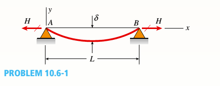
Assume that the deflected shape of a beam AB with immovable pinned supports (see figure) is given by the equation v = -
- For an aluminum-alloy beam with
E = 10 × 106 psi, calculate the tensile stress
Expert Solution & Answer

Trending nowThis is a popular solution!

Students have asked these similar questions
(Read image)
M16x2 grade 8.8 bolts No. 25 C1-
Q.2. The figure is a cross section of a grade 25 cast-iron pressure vessel. A
total of N, M16x2.0 grade 8.8 bolts are to be used to resist a separating
force of 160 kN. (a) Determine ks, km, and C. (b) Find the number of bolts
required for a load factor of 2 where the bolts may be reused when the joint 19 mm
is taken apart. (c) with the number of bolts obtained in (b), determine the
realized load factor for overload, the yielding factor of safety, and the
separation factor of safety.
19 mm
Problem4.
The thin uniform disk of mass m = 1-kg and radius R = 0.1m spins about the bent shaft OG with
the angular speed w2 = 20 rad/s. At the same time, the shaft rotates about the z-axis with the angular
speed 001 = 10 rad/s. The angle between the bent portion of the shaft and the z-axis is ẞ = 35°. The
mass of the shaft is negligible compared to the mass of the disk.
a. Find the angular momentum of the disk with respect to point G, based on the axis
orientation as shown. Include an MVD in your solution.
b. Find the angular momentum of the disk with respect to point O, based on the axis
orientation as shown. (Note: O is NOT the center of fixed-point rotation.)
c. Find the kinetic energy of the assembly.
z
R
R
002
2R
x
Answer: H = -0.046ĵ-0.040 kg-m²/sec
Ho=-0.146-0.015 kg-m²/sec
T 0.518 N-m
=
Chapter 10 Solutions
Bundle: Mechanics Of Materials, Loose-leaf Version, 9th + Mindtap Engineering, 1 Term (6 Months) Printed Access Card
Ch. 10 - A propped cantilever steel beam is constructed...Ch. 10 - A fixed-end b earn is subjected to a point load at...Ch. 10 - A propped cantilever beam AB of a length L is...Ch. 10 - A fixed-end beam AB of a length L supports a...Ch. 10 - A cantilever beam AB of a length L has a fixed...Ch. 10 - A cantilever beam of a length L and loaded by a...Ch. 10 - A cantilever beam has a length L and is loaded by...Ch. 10 - A propped cantilever beam of a length L is loaded...Ch. 10 - A propped cantilever beam of a length L is loaded...Ch. 10 - A fixed-end beam of a length L is loaded by a...
Ch. 10 - A fixed-end b earn of a length L is loaded by a...Ch. 10 - A fixed-end beam of a length L is loaded by...Ch. 10 - A counterclockwise moment M0acts at the midpoint...Ch. 10 - A propped cantilever beam of a length L is loaded...Ch. 10 - A propped cantilever beam is subjected to uniform...Ch. 10 - Repeat Problem 10.3-15 using L = 3.5 m, max = 3...Ch. 10 - A two-span, continuous wood girder (E = 1700 ksi)...Ch. 10 - A fixed-end beam AB carries point load P acting at...Ch. 10 - A fixed-end beam AB supports a uniform load of...Ch. 10 - -4-4 A cantilever beam is supported at B by cable...Ch. 10 - A propped cantilever beam AB of a length L carries...Ch. 10 - A beam with a sliding support at B is loaded by a...Ch. 10 - A propped cantilever beam of a length 2L with a...Ch. 10 - The continuous frame ABC has a pin support at /l,...Ch. 10 - The continuous frame ABC has a pin support at A,...Ch. 10 - Beam AB has a pin support at A and a roller...Ch. 10 - The continuous frame ABCD has a pin support at B:...Ch. 10 - Two flat beams AB and CD, lying in horizontal...Ch. 10 - -4-13 A propped cantilever beam of a length 2L is...Ch. 10 - A propped cantilever beam of a length 2L is loaded...Ch. 10 - Determine the fixed-end moments (MAand MB) and...Ch. 10 - A continuous beam ABC wit h two unequal spans, one...Ch. 10 - Beam ABC is fixed at support A and rests (at point...Ch. 10 - A propped cantilever beam has flexural rigidity EI...Ch. 10 - A triangularly distributed 1oad with a maximum...Ch. 10 - A fixed-end beam is loaded by a uniform load q =...Ch. 10 - Uniform load q = 10 lb/ft acts over part of the...Ch. 10 - A propped cantilever beam with a length L = 4 m is...Ch. 10 - A cant i levé r b ea m i s supported by a tie rod...Ch. 10 - The figure shows a nonprismatic, propped...Ch. 10 - A beam ABC is fixed at end A and supported by beam...Ch. 10 - A three-span continuous beam A BCD with three...Ch. 10 - A beam rests on supports at A and B and is loaded...Ch. 10 - A propped cantilever beam is subjected to two...Ch. 10 - A propped cantilever beam is loaded by a...Ch. 10 - A fixed-end beam AB of a length L is subjected to...Ch. 10 - A temporary wood flume serving as a channel for...Ch. 10 - Two identical, simply supported beams AB and CD...Ch. 10 - The cantilever beam AB shown in the figure is an...Ch. 10 - The beam AB shown in the figure is simply...Ch. 10 - The continuous frame ABC has a fixed support at A,...Ch. 10 - The continuous frame ABC has a pinned support at...Ch. 10 - A wide-flange beam ABC rests on three identical...Ch. 10 - A fixed-end beam AB of a length L is subjected to...Ch. 10 - A beam supporting a uniform load of intensity q...Ch. 10 - A thin steel beam AB used in conjunction with an...Ch. 10 - Find an expression for required moment MA(in terms...Ch. 10 - Repeat Problem 10.4-41 for the loading shown in...Ch. 10 - A propped cantilever beam is loaded by two...Ch. 10 - A cable CD of a length H is attached to the third...Ch. 10 - A propped cantilever beam, fixed at the left-hand...Ch. 10 - Solve t he preceding problem by integrating the...Ch. 10 - A two-span beam with spans of lengths L and L/3 is...Ch. 10 - Solve the preceding problem by integrating the...Ch. 10 - Assume that the deflected shape of a beam AB with...Ch. 10 - (a) A simple beam AB with length L and height h...
Knowledge Booster


Learn more about
Need a deep-dive on the concept behind this application? Look no further. Learn more about this topic, mechanical-engineering and related others by exploring similar questions and additional content below.Similar questions
- Problem 3. The assembly shown consists of a solid sphere of mass m and the uniform slender rod of the same mass, both of which are welded to the shaft. The assembly is rotating with angular velocity w at a particular moment. Find the angular momentum with respect to point O, in terms of the axes shown. Answer: Ñ。 = ½mc²wcosßsinßĵ + (}{mr²w + 2mb²w + ½ mc²wcos²ß) k 3 m r b 2 C لا marrow_forwardOnly question 2arrow_forwardOnly question 1arrow_forward
- Only question 3arrow_forwardI have Euler parameters that describe the orientation of N relative to Q, e = -0.7071*n3, e4 = 0.7071. I have Euler parameters that describe the orientation of U relative to N, e = -1/sqrt(3)*n1, e4 = sqrt(2/3). After using euler parameter rule of successive rotations, I get euler parameters that describe the orientation of U relative to Q, e = -0.4082*n1 - 0.4082*n2 - 0.5774*n3. I need euler parameters that describe the orientation of U relative to Q in vector basis of q instead of n. How do I get that?arrow_forwardDescribe at least 4 processes in engineering where control charts are (or should be) appliedarrow_forward
- Describe at least two (2) processes where control charts are (or should be) applied.arrow_forwardProblem 3: A cube-shaped spacecraft is in a circular Earth orbit. Let N (n,) be inertial and the spacecraft is denoted S (ŝ₁). The spacecraft is described such that ¯½º = J ŝ₁ŝ₁ + J ŝ₂§₂ + J §¸Ŝ3 Location of the spacecraft in the orbit is determined by the orbit-fixed unit vectors ê, that are oriented by the angle (Qt), where is a constant angular rate. 52 €3 3> 2t 55 Λ Из At the instant when Qt = 90°, the spacecraft S is oriented relative to the orbit such that 8₁ = 0° Space-three 1-2-3 angles 0₂ = 60° and ES = $₂ rad/s 0₁ = 135° (a) At this instant, determine the direction cosine matrix that describes the orientation of the spacecraft with respect to the inertial frame N.arrow_forwardThis problem illustrates that the factor of safety for a machine element depends on the particular point selected for analysis. Here you are to compute factors of safety, based upon the distortion-energy theory, for stress elements at A and B of the member shown in the figure. This bar is made of AISI 1006 cold-drawn steel and is loaded by the forces F = 1.100 kN, P = 8.00 kN, and T = 50.00 N-m. Given: Sy = 280 MPa. B -100 mm- 15-mm D. a) Determine the value of the axial stress at point B. b) Determine the value of the shear stress at point B. c) Determine the value of the Von Mises stress at point B. P Farrow_forward
- A piston-cylinder device initially contains 0.08 m^3 of nitrogen gas at 130 kPa and 170°C. The nitrogen is expanded to a pressure of 80 kPa via isentropic expansion. Determine the final temperature and the boundary work done by the system during this process.arrow_forwardA Carnot (ideal) heat pump is to be used to heat a house and maintain it at 22°C in winter. On a day when the average outdoor temperature remains at about 0°C, the house is estimated to lose heat at a rate of 65,000 kJ/h. If the heat pump consumes 6 kW of power while operating, determine: (a) how long the heat pump ran on that day (b) the total heating costs, assuming an average price of 11¢/kWh for electricity (c) the heating cost for the same day if an 85% efficient electric furnace is used instead of a heat pump.arrow_forwardFrom the information in the image, I needed to find the orientation of U relative to Q in vector basis q_hat. I transformed the euler angle/axis representation to euler parameters. Then I got its conjugate in order to get the euler parameter in N frame relative to Q. The problem gave the euler angle/axis representation in Q frame relative to N, so I needed to find the conjugate. Then I used the euler parameter rule of successive rotation to find the final euler parameters that describe the orientation of U relative to Q. However that orientation is in n_hat which is the intermediate frame. How do I get the final result in q_hat?arrow_forward
arrow_back_ios
SEE MORE QUESTIONS
arrow_forward_ios
Recommended textbooks for you
 Mechanics of Materials (MindTap Course List)Mechanical EngineeringISBN:9781337093347Author:Barry J. Goodno, James M. GerePublisher:Cengage Learning
Mechanics of Materials (MindTap Course List)
Mechanical Engineering
ISBN:9781337093347
Author:Barry J. Goodno, James M. Gere
Publisher:Cengage Learning
Mechanics of Materials Lecture: Beam Design; Author: UWMC Engineering;https://www.youtube.com/watch?v=-wVs5pvQPm4;License: Standard Youtube License