Principles of Geotechnical Engineering (MindTap Course List)
9th Edition
ISBN: 9781305970939
Author: Braja M. Das, Khaled Sobhan
Publisher: Cengage Learning
expand_more
expand_more
format_list_bulleted
Concept explainers
Textbook Question
Chapter 10, Problem 10.21P
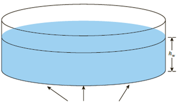
Refer to Figure 10.48. If R = 4 m and hw = height of water = 5 m, determine the vertical stress increases 2 m below the loaded area at radial distances where r = 0, 2, 4, 6, and 8 m.

Circular contact area of radius R on the ground surface
Figure 10.48
Expert Solution & Answer
Want to see the full answer?
Check out a sample textbook solution
Students have asked these similar questions
A composite beam is fabricated by bolting two 3.1-in.-wide by 14-in.-deep timber planks to the sides of a 0.4-in. by 14-in. steel plate.
The moduli of elasticity of the timber and the steel are 1940 ksi and 30300 ksi, respectively. The simply supported beam spans a
distance of 21 ft and carries two concentrated loads P, which are applied as shown. Assume LAB = LCD = 5 ft, Lgc = 11 ft, b = 3.1 in., d = 14
in. and t = 0.4 in.
(a) Determine the maximum bending stresses σ,, σ, produced in the timber planks and the steel plate if P = 2.1 kips.
(b) Assume that the allowable bending stresses of the timber and the steel are 830 psi and 24900 psi, respectively. Determine the
largest acceptable magnitude for concentrated loads P. (You may neglect the weight of the beam in your calculations.)
LAB
B
Answers:
LCD
LBC
b
Cross section
D
ksi, σ, =
i
ksi.
(a) σ,
=
(b) P= i
i
kips.
The internal shear force at a certain section of a steel beam is V = 107 kips. If the beam has the cross section shown, determine the
shear stress at point H, which is located 2 in. below the top surface of the flanged shape. The centroid is 5.283 in. above the bottom
surface of the beam, and the moment of inertia about the z axis is 465.8 in.4.
5 in.
2 in.
H
业
1 in.
1 in.
12 in.
8 in.
1 in.
11.51 ksi
O 9.72 ksi
8.34 ksi
6.03 ksi
○ 7.73 ksi
The beam shown will be constructed from a standard steel W-shape using an allowable bending stress of 33.6 ksi. Assume P = 70 kips.
L₁ = 2.2 ft, and L2 = 6.6 ft.
(a) Determine the minimum section modulus required for this beam.
(b) From the table below, select the lightest W shape that can be used for this beam.
(c) What is the total weight of the steel beam itself (ie, not including the loads that are carried by the beam)?
Lu
B
D
L2
L₁
Wide-Flange Sections or W Shapes-U.S. Customary Units
x
x
be
Web
Area Depth thickness
Flange
width
Flange
thickness
Designation
A
d
Tw
by
4
S₁
و"
in.²
in.
in.
in.
in.
in,4
in.³
in.
in.4
in,³
in.
W24 x 94
27.7
24.3
0.515
9.07
0.875
2700
222
9.87
109
24.0
1.98
24 x 76
22.4
23.9
0.440
8.99
0.680
2100
176
9.69
82.5
18.4
1.92
24 x 68
20.1
23.7
0.415
8.97
0.585
1830
154
9.55
70.4
15.7
1.87
24 x 55
16.2
23.6
0.395
7.01
0.505
1350
114
9.11
29.1
8.30
1.34
W21 x 68
20.0
21.1
0.430
8.27
0.685
1480
140
8.60
64.7
15.7
1.80
21 x 62
18.3
21.0
0.400
8.24
0.615
1330
127…
Chapter 10 Solutions
Principles of Geotechnical Engineering (MindTap Course List)
Ch. 10 - Prob. 10.1PCh. 10 - Prob. 10.2PCh. 10 - Prob. 10.3PCh. 10 - Prob. 10.4PCh. 10 - Prob. 10.5PCh. 10 - Prob. 10.6PCh. 10 - Point loads of magnitude 125, 250, and 500 kN act...Ch. 10 - Refer to Figure 10.41. Determine the vertical...Ch. 10 - For the same line loads given in Problem 10.8,...Ch. 10 - Refer to Figure 10.41. Given: q2 = 3800 lb/ft, x1...
Ch. 10 - Refer to Figure 10.42. Due to application of line...Ch. 10 - Refer to Figure 10.43. A strip load of q = 1450...Ch. 10 - Repeat Problem 10.12 for q = 700 kN/m2, B = 8 m,...Ch. 10 - Prob. 10.14PCh. 10 - For the embankment shown in Figure 10.45,...Ch. 10 - Refer to Figure 10.46. A flexible circular area of...Ch. 10 - Refer to Figure 10.47. A flexible rectangular area...Ch. 10 - Refer to the flexible loaded rectangular area...Ch. 10 - Prob. 10.19PCh. 10 - Prob. 10.20PCh. 10 - Refer to Figure 10.48. If R = 4 m and hw = height...Ch. 10 - Refer to Figure 10.49. For the linearly increasing...Ch. 10 - EB and FG are two planes inside a soil element...Ch. 10 - A soil element beneath a pave ment experiences...
Knowledge Booster
Learn more about
Need a deep-dive on the concept behind this application? Look no further. Learn more about this topic, civil-engineering and related others by exploring similar questions and additional content below.Similar questions
- A composite beam is made of two brass [E=114 GPa] bars bonded to two aluminum [E = 74 GPa] bars, as shown. The beam is subjected to a bending moment of 335 N-m acting about the z axis. Using a = 5 mm, b = 30 mm, c = 10 mm, and d = 20 mm, calculate (a) the maximum bending stress in the aluminum bars. (b) the maximum bending stress in the brass bars. N Aluminum C Brass Brass Aluminum b Answers: (a) σal= (b) Obr= a a MPa MPaarrow_forwardA standard steel pipe (D = 3.500 in.; d = 3.068 in.) supports a concentrated load of P = 630 lb as shown. The span length of the cantilever beam is L = 4 ft. Determine the magnitude of the maximum horizontal shear stress in the pipe. 720 psi 761 psi 508 psi 564 psi 667 psi L Pipe cross section.arrow_forwardA beam is subjected to equal bending moments of M₂ = 59 kip-ft. The cross-sectional dimensions are b₁ = 7.5 in., d₁ = 1.4 in., b₂ = 0.55 in., d₂ = 5.0 in., b3 = 3.2 in., and d3 = 1.5 in. Determine: (a) the centroid location (measured with respect to the bottom of the cross-section), the moment of inertia about the z axis, and the controlling section modulus about the z axis. (b) the bending stress at point H. Tensile stress is positive, while compressive stress is negative. (c) the bending stress at point K. Tensile stress is positive, while compressive stress is negative. (d) the maximum bending stress produced in the cross section. Tensile stress is positive, while compressive stress is negative. M₂ Z M₂ Answer: (a) y= i Iz= in. in.4 S= i on,3 (b) σH= i ksi (c) OK = i ksi (d) σmax= ksi K b₁ d₁ H b₂ b3 d₂ d3arrow_forward
- A cantilever timber beam with a span of L = 2.9 m supports a uniformly distributed load w. The beam width is b = 300 mm and the beam height is h = 160 mm. The allowable bending stress of the wood is 7 MPa. Determine the magnitude of the maximum load w that may be carried by the beam. Answer: w= I i kN/m.arrow_forwardAW18 × 40 standard steel shape is used to support the loads shown on the beam. Assume P = 24 kips, w = 4.4 kips/ft, LAB = 4.6 ft, LBC = 4.6 ft, and LCD = 15.0 ft. Determine the magnitude of the maximum bending stress in the beam. B C Answer: LAB ✓ LBC Omax i ksi W LCD xarrow_forwardA simply supported timber beam carries a uniformly distributed load of w = 3 kN/m. Determine the magnitude of the largest horizontal shear stress at point H, which is 60 mm above the centroid, anywhere along the length of the beam. 293 kPa 234 kPa 252 kPa 321 kPa ○ 163 kPa พ 4 m 300 mm B 1 m 100 mm K 60 mm * 75 mmarrow_forward
- The "New Jersey" barrier is commonly used during highway construction. Determine its weight per foot of length if it is made from plain stone concrete. 4 in. 75°- 12 in. 55° 6 in. -24 inarrow_forwardThe "New Jersey" barrier is commonly used during highway construction. Determine its weight per foot of length if it is made from plain stone concrete. 4 in. 75°- 55° 12 in. 6 in. 24 inarrow_forwardThe prestressed concrete girder is made from plain stone concrete and four -in. cold form steel reinforcing rods. Determine the dead weight of the girder per foot of its length. 8 in. 6 in. 20 in. 6 in. 8 in. 4 in. 6 in. 4 in.arrow_forward
- The floor of a building, shown in Fig. (a), is subjected to a uniformly distributed load of 3.5 kPa over its surface area. Determine the loads acting on all the members of the floor system. AI Column Floor beam B Slab C D 3 at 4 m = 12 m Floor beam E F Girder GT -9 m. (a) Framing Planarrow_forwardCommercial trucks begin to arrive at a seaport entry plaza at 7:50 A.M., at the rate of λ(t) = 6.3 – 0.25t[λ(t) is in veh/min and t is in minutes]. The plaza opens at 8:00 A.M. For the first 10 minutes, one processing booth is open. After the first 10 minutes until the queue clears, two processing booths are open. Each booth processes trucks at a uniform rate of two per minute. What is the average delay per vehicle, the maximum queue length, and the average queue length?arrow_forwardThe floor system of a gymnasium consists of a 130-mm-thick concrete slab resting on four steel beams (A = 9100 mm²) that, in turn, are supported by two steel girders (A = 25600 mm²), as shown in Fig. 2.3. Determine the dead loads acting on beam BF and girder AD. 2.3 Beam BF Uniformly distributed load ㅋㅋ =28.6 (5) (180) + 77 (100) = 16.04 kN/m 16.04 kN/m B 80.2 kN F 80.2 kN.arrow_forward
arrow_back_ios
SEE MORE QUESTIONS
arrow_forward_ios
Recommended textbooks for you
 Principles of Geotechnical Engineering (MindTap C...Civil EngineeringISBN:9781305970939Author:Braja M. Das, Khaled SobhanPublisher:Cengage Learning
 Principles of Foundation Engineering (MindTap Cou...Civil EngineeringISBN:9781305081550Author:Braja M. DasPublisher:Cengage Learning
 Fundamentals of Geotechnical Engineering (MindTap...Civil EngineeringISBN:9781305635180Author:Braja M. Das, Nagaratnam SivakuganPublisher:Cengage Learning
 Principles of Foundation Engineering (MindTap Cou...Civil EngineeringISBN:9781337705028Author:Braja M. Das, Nagaratnam SivakuganPublisher:Cengage Learning

Principles of Geotechnical Engineering (MindTap C...
Civil Engineering
ISBN:9781305970939
Author:Braja M. Das, Khaled Sobhan
Publisher:Cengage Learning

Principles of Foundation Engineering (MindTap Cou...
Civil Engineering
ISBN:9781305081550
Author:Braja M. Das
Publisher:Cengage Learning

Fundamentals of Geotechnical Engineering (MindTap...
Civil Engineering
ISBN:9781305635180
Author:Braja M. Das, Nagaratnam Sivakugan
Publisher:Cengage Learning

Principles of Foundation Engineering (MindTap Cou...
Civil Engineering
ISBN:9781337705028
Author:Braja M. Das, Nagaratnam Sivakugan
Publisher:Cengage Learning
Stress Distribution in Soils GATE 2019 Civil | Boussinesq, Westergaard Theory; Author: Gradeup- GATE, ESE, PSUs Exam Preparation;https://www.youtube.com/watch?v=6e7yIx2VxI0;License: Standard YouTube License, CC-BY