
Principles of Geotechnical Engineering (MindTap Course List)
9th Edition
ISBN: 9781305970939
Author: Braja M. Das, Khaled Sobhan
Publisher: Cengage Learning
expand_more
expand_more
format_list_bulleted
Concept explainers
Videos
Textbook Question
Chapter 10, Problem 10.1CTP
EB and FG are two planes inside a soil element ABCD as shown in Figure 10.50.
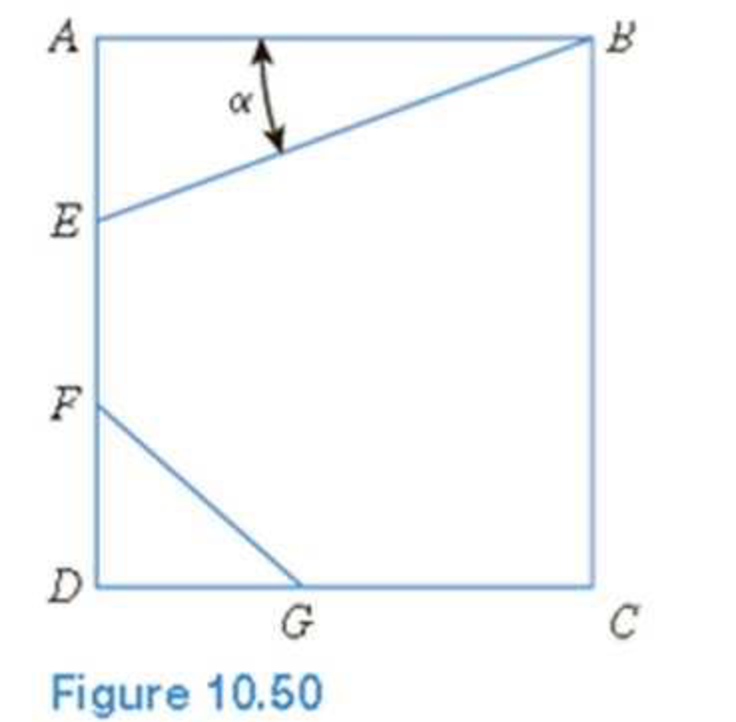
Stress conditions on the two planes are
Plane EB: σEB = 25 kN/m2; τEB = +10 kN/m2
Plane FG: σFG = 10 kN/m2; τFG = –5 kN/m2
(Note: Mohr’s circle sign conventions for stresses are used above)
Given α; = 25°, determine:
- a. The maximum and minimum principal stresses
- b. The angle between the planes EB and FG
- c. The external stresses on planes AB and BC that would cause the above internal stresses on planes EB and FG
Expert Solution & Answer

Trending nowThis is a popular solution!

Students have asked these similar questions
Find the length of the diagonal on
the x-z plane (square root of
square of sides).
Find angle between the vector F
and its projection on x-z (the
diagonal defined above).
Find Horizontal Projection of F on
x-z plane, Fh, and vertical
component, FY.
Find projections of Fh, to define
in-plane components Fx and Fz.
Show that results match those of
Problem 2(a) above.
(2,0,4)
F₂
100 N
(5, 1, 1)
For the control system Draw Nyquist Plot with
Solution
G(S)= 63.625 (S+1)(S+3)
S(S+2)(5+65+18) (5+5)
Q3:
Find the support reactions at A:
y
mm
A
P=last 2 student's ID#+100 (N)
124N
last 3 student's ID# (mm)
724mm
20 mm
D
B
C
X
last 3 student's ID#+20 mm
744mm
40 mm
60 mm
Chapter 10 Solutions
Principles of Geotechnical Engineering (MindTap Course List)
Ch. 10 - Prob. 10.1PCh. 10 - Prob. 10.2PCh. 10 - Prob. 10.3PCh. 10 - Prob. 10.4PCh. 10 - Prob. 10.5PCh. 10 - Prob. 10.6PCh. 10 - Point loads of magnitude 125, 250, and 500 kN act...Ch. 10 - Refer to Figure 10.41. Determine the vertical...Ch. 10 - For the same line loads given in Problem 10.8,...Ch. 10 - Refer to Figure 10.41. Given: q2 = 3800 lb/ft, x1...
Ch. 10 - Refer to Figure 10.42. Due to application of line...Ch. 10 - Refer to Figure 10.43. A strip load of q = 1450...Ch. 10 - Repeat Problem 10.12 for q = 700 kN/m2, B = 8 m,...Ch. 10 - Prob. 10.14PCh. 10 - For the embankment shown in Figure 10.45,...Ch. 10 - Refer to Figure 10.46. A flexible circular area of...Ch. 10 - Refer to Figure 10.47. A flexible rectangular area...Ch. 10 - Refer to the flexible loaded rectangular area...Ch. 10 - Prob. 10.19PCh. 10 - Prob. 10.20PCh. 10 - Refer to Figure 10.48. If R = 4 m and hw = height...Ch. 10 - Refer to Figure 10.49. For the linearly increasing...Ch. 10 - EB and FG are two planes inside a soil element...Ch. 10 - A soil element beneath a pave ment experiences...
Knowledge Booster


Learn more about
Need a deep-dive on the concept behind this application? Look no further. Learn more about this topic, civil-engineering and related others by exploring similar questions and additional content below.Similar questions
- A hoist trolley is subjected to the three forces shown. Knowing that α = 40°, determine (a) the required magnitude of the force P if the resultant of the three forces is to be vertical, (b) the corresponding magnißide of the resultant. α 724lb last 3 student's ID# lb α last 2 student's ID#+100 lb 124lb Parrow_forwardFive wood boards are bolted together to form the built-up beam shown in the figure. The beam is subjected to a shear force of V = 13 kips. Each bolt has a shear strength of Vbolt = 6 kips. [h₁ =4.25 in., t₁ = 0.5 in., h₂ = 6 in., t₂ = 1 in.] hi + hi/2 h:/2 h: 2 h + h/2 Determine the moment of inertia of the section. Determine the maximum allowable spacing of the bolts. Determine the shear flow in the section connected by fasteners.arrow_forwardA vessel has a diameter of 1m and 2m high is moving downward with a positive acceleration of 3m/s2. The pressure at the bottom of the liquid is 9.534kPa, determine the mass of the liquid.arrow_forward
- You are the engineer asked to design a rapid sand filtration system for a small water treatment plant. It has the following characteristics: Hydraulic loading rate = 6 m/h Total volumetric flow rate of the plant = 3 MGD Effective filtration rate = 5.8 m/h Production efficiency = 97% Complete (filtration, rinsing, and backwashing) filter cycle duration = 48 h What is the area of your square filtration system? What are the surface dimensions of the filter? What volume of water is needed for backwashing plus rinsing the filter in each rinsing cycle?arrow_forwardFive wood boards are bolted together to form the built-up beam shown in the figure. The beam is subjected to a shear force of V = 14 kips. Each bolt has a shear strength of V bolt = 6 kips. [h₁ = 4 in., t₁ = 0.75 in., h₂ = 6.5 in., t₂ = 1.25 in.] h/2 + hi/2 h:/2 h: 2 hi + hiz Determine the moment of inertia of the section. Calculate the shear force in each bolt. Calculate the shear stress in the bolts.arrow_forwardA box beam is fabricated from two plywood webs that are secured to lumber boards at its top and bottom flanges. The beam supports a concentrated load of P = 4100 lb at the center of a 13-ft span. Bolts (3/8-in. diameter) connect the plywood webs and the lumber flanges at a spacing of s = 9 in. along the span. Supports A and C can be idealized as a pin and a roller, respectively. [w = 4.5 in., b = 0.25 in., t = 5 in., h = 17 in.] B Determine the maximum horizontal shear stress in the plywood webs. Determine the average shear stress in the bolts. Determine the maximum bending stress in the lumber flanges.arrow_forward
- A cantilever flexural member is fabricated by bolting two identical C- section steel shapes back to back as shown in the figure. The beam has a span of L = 1300 mm and supports a concentrated load of P = 800 N. The cross-sectional dimensions of the built- up shape are shown in the figure. Assume the section has a constant thickness of t = 2.5 mm. Bolts of 3.5 mm diameter are installed at intervals of s = 65 mm.[b = 100 mm, a = 25 mm] b T Determine the shear flow in the sections connected by the fasteners. Calculate the shear force in each bolt. Calculate the shear stress in the bolts.arrow_forwardFive wood boards are bolted together to form the built-up beam shown in the figure. The beam is subjected to a shear force of V = 14 kips. Each bolt has a shear strength of V bolt = 6 kips. [h₁4 in., t₁ = 0.75 in., h₂ = 6.5 in., t₂ = 1.25 in.] hi/2 h/2 h2 h:/2 hi/2 + h2 Determine the moment of inertia of the section. Determine the shear flow in the section connected by fasteners. Determine the maximum allowable spacing of the bolts.arrow_forwardTwo built-up beams shown in the figure below have the same dimensions and are connected by the same types of nails with the same spacing. Which beam could carry more shear force if the controlling factor is the shear flow in the fasteners? Nails Beam (1) Z Beam (2) Beam (2) Beam (1) Both are the same Cannot answer without knowing the shear diagram Cannot answer without knowing the modulus of rigidity Nailsarrow_forward
- Two built-up beams shown in the figure below have the same dimensions and are connected by the same types of nails with the same spacing. Which beam could carry more shear force if the controlling factor is the shear flow in the fasteners? Nails Beam (1) Beam (2) Cannot answer without knowing the shear diagram Beam (1) Cannot answer without knowing the modulus of Nailsarrow_forward8-51. Determine the horizontal displacement at C. Take E = 29(10³) ksi, I = 150 in for each member. Use the method of virtual work. 8ft 10 ft Barrow_forward5. Problem 8-46 on Page 374. 8-46. The L-shaped frame is made from two fixed-connected segments. Determine the vertical displacement of the end C. Use the method of virtual work. El is constant. -9 ft- 2 k/ft 12 ftarrow_forward
arrow_back_ios
SEE MORE QUESTIONS
arrow_forward_ios
Recommended textbooks for you
 Principles of Geotechnical Engineering (MindTap C...Civil EngineeringISBN:9781305970939Author:Braja M. Das, Khaled SobhanPublisher:Cengage Learning
 Principles of Foundation Engineering (MindTap Cou...Civil EngineeringISBN:9781305081550Author:Braja M. DasPublisher:Cengage Learning
 Fundamentals of Geotechnical Engineering (MindTap...Civil EngineeringISBN:9781305635180Author:Braja M. Das, Nagaratnam SivakuganPublisher:Cengage Learning
 Principles of Foundation Engineering (MindTap Cou...Civil EngineeringISBN:9781337705028Author:Braja M. Das, Nagaratnam SivakuganPublisher:Cengage Learning
Principles of Geotechnical Engineering (MindTap C...
Civil Engineering
ISBN:9781305970939
Author:Braja M. Das, Khaled Sobhan
Publisher:Cengage Learning
Principles of Foundation Engineering (MindTap Cou...
Civil Engineering
ISBN:9781305081550
Author:Braja M. Das
Publisher:Cengage Learning
Fundamentals of Geotechnical Engineering (MindTap...
Civil Engineering
ISBN:9781305635180
Author:Braja M. Das, Nagaratnam Sivakugan
Publisher:Cengage Learning
Principles of Foundation Engineering (MindTap Cou...
Civil Engineering
ISBN:9781337705028
Author:Braja M. Das, Nagaratnam Sivakugan
Publisher:Cengage Learning
Stress Distribution in Soils GATE 2019 Civil | Boussinesq, Westergaard Theory; Author: Gradeup- GATE, ESE, PSUs Exam Preparation;https://www.youtube.com/watch?v=6e7yIx2VxI0;License: Standard YouTube License, CC-BY