Principles of Geotechnical Engineering (MindTap Course List)
9th Edition
ISBN: 9781305970939
Author: Braja M. Das, Khaled Sobhan
Publisher: Cengage Learning
expand_more
expand_more
format_list_bulleted
Concept explainers
Textbook Question
Chapter 10, Problem 10.18P
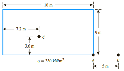
Refer to the flexible loaded rectangular area shown in Figure 10.47. Using Eq. (10.36), determine the vertical stress increase below the center of the loaded area at depths z = 3, 6, 9, 12, and 15 m.

Figure 10.47
Expert Solution & Answer
Trending nowThis is a popular solution!

Students have asked these similar questions
e
t
a
S
t
1
d
?
f
a
V
f
1
2.20 A driver is traveling at 90 mi/h down a 3%
grade on good, wet pavement. An accident
investigation team noted that braking skid marks
started 410 ft before a parked car was hit at an
estimated 45 mi/h. Ignoring air resistance, and using
theoretical stopping distance, what was the braking
efficiency of the car?
2.21 A small truck is to be driven down a 4% grade
at 70 mi/h. The coefficient of road adhesion is 0.95,
and it is known that the braking efficiency is 80%
when the truck is empty and decreases by one
percentage point for every 100 lb of cargo added.
Ignoring aerodynamic resistance, if the driver wants
the truck to be able to achieve a minimum
theoretical stopping distance of 275 ft from the
point of brake application, what is the maximum
amount of cargo (in pounds) that can be carried?
2.32 A driver is traveling at 52 mi/h on a wet road.
An object is spotted on the road 415 ft ahead and the
driver is able to come to a stop just before hitting the
object. Assuming standard perception/reaction time
and practical stopping distance, determine the grade
of the road.
The pumping system shown below is supposed to provide at least 250 GPM of water to the
drinking trough. The outlet of the drawn tubing at the drinking water trough discharges to the
atmosphere as a water jet. The outlet of the pipe is approximately 12 ft higher than the water
surface of reservoir. Expected water temperature is 70ᵒF. Your objective is to select a pump
and check its performance for the specified system. Your tasks include:
1. Determine total dynamic head (TDH) operating against the pump for the design flow rate.
Neglect minor losses. Note that H-W is not appropriate for this water temperature, and you
need to use D-W.
2. Use the TDH and Qdesign to approach a pump vendor. She provides you the attached four
pump performance curves for your consideration.
3. Select the appropriate pump based on the fit of the selection point on the pump
performance curves.
4. Develop the system curve.
5. Determine the pump operating point and record the system operating conditions…
Chapter 10 Solutions
Principles of Geotechnical Engineering (MindTap Course List)
Ch. 10 - Prob. 10.1PCh. 10 - Prob. 10.2PCh. 10 - Prob. 10.3PCh. 10 - Prob. 10.4PCh. 10 - Prob. 10.5PCh. 10 - Prob. 10.6PCh. 10 - Point loads of magnitude 125, 250, and 500 kN act...Ch. 10 - Refer to Figure 10.41. Determine the vertical...Ch. 10 - For the same line loads given in Problem 10.8,...Ch. 10 - Refer to Figure 10.41. Given: q2 = 3800 lb/ft, x1...
Ch. 10 - Refer to Figure 10.42. Due to application of line...Ch. 10 - Refer to Figure 10.43. A strip load of q = 1450...Ch. 10 - Repeat Problem 10.12 for q = 700 kN/m2, B = 8 m,...Ch. 10 - Prob. 10.14PCh. 10 - For the embankment shown in Figure 10.45,...Ch. 10 - Refer to Figure 10.46. A flexible circular area of...Ch. 10 - Refer to Figure 10.47. A flexible rectangular area...Ch. 10 - Refer to the flexible loaded rectangular area...Ch. 10 - Prob. 10.19PCh. 10 - Prob. 10.20PCh. 10 - Refer to Figure 10.48. If R = 4 m and hw = height...Ch. 10 - Refer to Figure 10.49. For the linearly increasing...Ch. 10 - EB and FG are two planes inside a soil element...Ch. 10 - A soil element beneath a pave ment experiences...
Knowledge Booster
Learn more about
Need a deep-dive on the concept behind this application? Look no further. Learn more about this topic, civil-engineering and related others by exploring similar questions and additional content below.Similar questions
- $$ 5.1 Assume that you are observing traffic in a single lane of a highway at a specific location. You measure the average headway and average spacing of passing vehicles as 3.2 seconds and 165 ft, respectively. Calculate the flow, average speed, and density of the traffic stream in this lane. 5.2 Assume that you are an observer standing at a point along a three-lane roadway. All vehicles in lane 1 are traveling at 30 mi/h, all vehicles in lane 2 are traveling at 45 mi/h, and all vehicles in lane 3 are traveling at 60 mi/h. There is also a constant spacing of 0.5 mile between vehicles. If you collect spot speed data for all vehicles as they cross your observation point, for 30 minutes, what will be the time-mean speed and space-mean speed for this traffic stream?arrow_forwardDetermine the direction of F2 such that the resultant force of adding F1 and F2 acts along the positive yaxis.arrow_forward3 decimal places answer don't use aiarrow_forward
- 4.5 in 2.5 in. D B1 0 140 lb 5 in. 40° 20 lb Replace the forces acting at A and D with an equivalent force-couple system acting at point B. Force B = acting at a angle measured from the Submit part Couple M= in the direction. answered Submit partarrow_forward4.5 in. 2.5 in. 140 lb B Only handwritten 5 in. 40° 120 lb Replace the forces acting at A and D with an equivalent force-couple system acting at point B. Force B = acting at a angle measured from the Submit part Couple M= in the direction. Unansweredarrow_forward1.) Calculate the internal forces and moments (shear force, bending moment, and axial force if applicable) at point C on the beam shown below. Clearly show all your steps, including the calculation of support reactions, and the determination of internal loadings at point C. (Ans: Nc = 0 kN, Vc = -6.53 kN, Mc = 71.68 kN.m) 40 pts. 7.5 kN A H 6.0 kN/m 4.0 kN 4.0 C B 2.0 3.0 7.0 1.5 2.0arrow_forward
- Please solve using cartesian coordinates. Be clear about why cos or sin is used (explain the trig). Make sure to account for the normal force.arrow_forwardSolve /Draw the shear force and bending moment for these Don't use Artificial intelligencearrow_forwardA For the gravity concrete dam shown in the figure, the following data are available: -The factor of safety against sliding (F.S sliding) =1.2 - Unit weight of concrete (Yeone) 24 KN/m³ - Neglect( Wave pressure, silt pressure, ice force and earth quake force) H=0.65, (Ywater)= 9.81 KN/m³ Find factor of safety against overturning (F.S overturning) 10m 5m 6m 80marrow_forward
- Draw the shear force and bending moment diagramarrow_forwardThe pin-connected structure consists of a rigid beam ABCD and two supporting bars. Bar (1) is an aluminum alloy [E = 75 GPa] with a cross-sectional area of A₁ = 850 mm². Bar (2) is a bronze alloy [E = 109 GPa] with a cross-sectional area of A₂ = 410 mm². Assume L₁=2.6 m, L₂-3.3 m, a=0.7 m, b=1.5 m, and c=0.8 m. All bars are unstressed before the load P is applied; however, there is a 4.5-mm clearance in the pin connection at A. If a load of P = 45 kN is applied at B, determine: (a) the normal stresses σ1,02, in both bars (1) and (2). (b) the normal strains €1, €2, in bars (1) and (2). (c) determine the downward deflection VA of point A on the rigid bar. (1) Answers: a (a) σ1 = (b) E₁ = (C) VA = i i i ล B C L2 b C MPa, σ = i με, Ε2 i mm. MPa. μεarrow_forwardThe pin-connected structure consists of a rigid beam ABCD and two supporting bars. Bar (1) is an aluminum alloy [E = 79 GPa] with a cross-sectional area of A₁ = 780 mm². Bar (2) is a bronze alloy [E = 104 GPa] with a cross-sectional area of A₂ = 460 mm². Assume L₁=1.6 m, L₂-2.1 m, a=0.6 m, b=1.8 m, and c-1.3 m. All bars are unstressed before the load P is applied; however, there is a 4-mm clearance in the pin connection at A. If a load of P = 58 kN is applied at B, determine: (a) the normal stresses 01,02, in both bars (1) and (2). (b) the normal strains €1,2, in bars (1) and (2). (c) determine the downward deflection VA of point A on the rigid bar. (1) L₁ B Answers: (a)σ = b ล L2 C D i MPa, σ1 = i MPa. με, Ε2 = i με. (b) €1 = i (C) VA = i mm.arrow_forward
arrow_back_ios
SEE MORE QUESTIONS
arrow_forward_ios
Recommended textbooks for you
 Principles of Geotechnical Engineering (MindTap C...Civil EngineeringISBN:9781305970939Author:Braja M. Das, Khaled SobhanPublisher:Cengage Learning
 Principles of Foundation Engineering (MindTap Cou...Civil EngineeringISBN:9781305081550Author:Braja M. DasPublisher:Cengage Learning
 Fundamentals of Geotechnical Engineering (MindTap...Civil EngineeringISBN:9781305635180Author:Braja M. Das, Nagaratnam SivakuganPublisher:Cengage Learning
 Principles of Foundation Engineering (MindTap Cou...Civil EngineeringISBN:9781337705028Author:Braja M. Das, Nagaratnam SivakuganPublisher:Cengage Learning

Principles of Geotechnical Engineering (MindTap C...
Civil Engineering
ISBN:9781305970939
Author:Braja M. Das, Khaled Sobhan
Publisher:Cengage Learning

Principles of Foundation Engineering (MindTap Cou...
Civil Engineering
ISBN:9781305081550
Author:Braja M. Das
Publisher:Cengage Learning

Fundamentals of Geotechnical Engineering (MindTap...
Civil Engineering
ISBN:9781305635180
Author:Braja M. Das, Nagaratnam Sivakugan
Publisher:Cengage Learning

Principles of Foundation Engineering (MindTap Cou...
Civil Engineering
ISBN:9781337705028
Author:Braja M. Das, Nagaratnam Sivakugan
Publisher:Cengage Learning
Stress Distribution in Soils GATE 2019 Civil | Boussinesq, Westergaard Theory; Author: Gradeup- GATE, ESE, PSUs Exam Preparation;https://www.youtube.com/watch?v=6e7yIx2VxI0;License: Standard YouTube License, CC-BY