Principles of Geotechnical Engineering (MindTap Course List)
9th Edition
ISBN: 9781305970939
Author: Braja M. Das, Khaled Sobhan
Publisher: Cengage Learning
expand_more
expand_more
format_list_bulleted
Concept explainers
Textbook Question
Chapter 10, Problem 10.9P
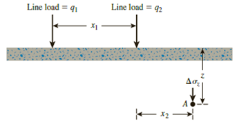
For the same line loads given in Problem 10.8, determine the vertical stress increase, Δσz, at a point located 4 m below the line load, q2.
Refer to Figure 10.41. Determine the vertical stress increase, Δσz, at point A with the following values: q1 = 110 kN/m, q2 = 440 kN/m, x1 = 6 m, x2 = 3 m, and z = 4 m.

Figure 10.41
Expert Solution & Answer
Want to see the full answer?
Check out a sample textbook solution
Students have asked these similar questions
Given the following end areas for cut & fill, complete the eart
calculation using a shrinkage of 10%. Then draw the M.H.D. and the longitudinal pro
of the earthworks & find the following:
a) Limit of Economic Haul (L.E.H.).
b) Freehaul volume (F.H.V.).
c) Overhaul volume (O.H.V.).
d) Waste volume.
e) Borrow volume.
f) Total cost of the earthworks.
Given that:
-Cost of overhaul = 30 ID/m².station.
-Cost of borrow-120 ID/m³.
- Cost of freehaul - 70 ID/m².
-Freehaul Distance (F.H.D.)- 200m-2 stations.
Areas (m²)
Station
Volumes (m)
Cut Fill Cut+
Fill-
0
10
Corrected
Fill-
1100
1
12
1300
2
14
1500
3
146
1500
14
350
550
250
275
10
5
16
96
1300
1430
6
1500
1650
14
7
1300
1430
12
S
.
1000
1100
8
9
300 200
220
12
10
1400
16
11
Calculate the clean bed head loss for a filter consisting of uniformly graded sphere silica beads (shape factor p = 1), all having a diameter
of 1 mm, packed into a 5 m x 5 m filter bed with depth D = 8 m, with a bed porosity of ε = 0.4, treating a flow rate of 0.025 m³/s. Assume a
viscosity of 1.25x10⁻⁶ m2/s. Report your answer with the units of meters and round to the nearest 0.1.
Using the book Olin's Construction: Principles, Materials, and Methods
By H. Leslie SimmonsUsing Materials for a Small Residential House
Compile A detailed list of every single material used in the construction of this small Residential Home.
Your list will be
broken up into 5 stages FOUNDATION, FRAMING, ROUGH IN, ROOF, FINISH
You do not need to estimate the quantity of materials.
Choose the exterior and interior finishes. Find
3
SDS sheets for materialsfor each stage of the build
.
REMEMBER EVERY ITEM MISSED IN AN ESTIMATE WILL COST YOU MONEY.
HOUSE DETAILS
•
Slab foundation
•
UTILITIES
AND GROUND WORK IS COMPLETED
.
•
Single Story
•
Copper plumbing
or PEX
2x6 Wood Framing
Gas Water Heater
Gas appliances
ROOF:
asphalt shingles
,
Stick framing, Cross hipped roof
House has
Heating and
A/C
EXAMPLE:
FOUNDATION
Concrete
Wood For forms
Chapter 10 Solutions
Principles of Geotechnical Engineering (MindTap Course List)
Ch. 10 - Prob. 10.1PCh. 10 - Prob. 10.2PCh. 10 - Prob. 10.3PCh. 10 - Prob. 10.4PCh. 10 - Prob. 10.5PCh. 10 - Prob. 10.6PCh. 10 - Point loads of magnitude 125, 250, and 500 kN act...Ch. 10 - Refer to Figure 10.41. Determine the vertical...Ch. 10 - For the same line loads given in Problem 10.8,...Ch. 10 - Refer to Figure 10.41. Given: q2 = 3800 lb/ft, x1...
Ch. 10 - Refer to Figure 10.42. Due to application of line...Ch. 10 - Refer to Figure 10.43. A strip load of q = 1450...Ch. 10 - Repeat Problem 10.12 for q = 700 kN/m2, B = 8 m,...Ch. 10 - Prob. 10.14PCh. 10 - For the embankment shown in Figure 10.45,...Ch. 10 - Refer to Figure 10.46. A flexible circular area of...Ch. 10 - Refer to Figure 10.47. A flexible rectangular area...Ch. 10 - Refer to the flexible loaded rectangular area...Ch. 10 - Prob. 10.19PCh. 10 - Prob. 10.20PCh. 10 - Refer to Figure 10.48. If R = 4 m and hw = height...Ch. 10 - Refer to Figure 10.49. For the linearly increasing...Ch. 10 - EB and FG are two planes inside a soil element...Ch. 10 - A soil element beneath a pave ment experiences...
Knowledge Booster
Learn more about
Need a deep-dive on the concept behind this application? Look no further. Learn more about this topic, civil-engineering and related others by exploring similar questions and additional content below.Similar questions
- A1.4- Determine the factored moment resistance for the flanged beam (simply supported) shown in Figure 4. Given: Beam span L = 8m fc = 25MPa fy=400MPa As = 3-35M *350* mm 1.5 m Figure 4 *350* mm -60mmarrow_forwardA2.3- a simply supported reinforced concrete beam of rectangular cross-section is shown in Figure 3. The beam supports a uniform dead load of 20 kN/m (excluding the beam self-weight) and a uniform live load of 20 kN/m. The beam width is restricted to 400 mm. The maximum aggregate size is 20 mm. We are using 10M bars for stirrups and 25M bars for tension steel. Concrete is type N with f'c = 35 MPa and fy = 400 MPa. The beam needs to have 2hr fire rating. Design the beam for the given load, considering the reinforcement ratio p < 0.5 pb Figure 3 WDL = 20 kN/m WLL= 20 kN/m 8.0 marrow_forwardOlin's Construction: Principles, Materials, and Methods By H. Leslie Simmonsarrow_forward
- The L6 x 4 x 1/2 single angle shown has two rows of bolts. Each leg has one row (one line) of 5/8 in bolts in each leg as shown. Determine the net area (An). If needed, I attached the section properties from AISC manual for L6x4x1/2.arrow_forward3. Determine the reactions at the supports for the frame shown in following. 36.5 kN/m 14.6 kN/m Hinge R = 10 m 10 m -10 marrow_forward# 4 F3 Existing Flocculation Basin Design Parameters at 22.5 MGD: A) # of Basins: 5 B) # of Stages per Basin: 2 c) Basin Dimensions: (30 ft. X 4 ft. X 15 ft.) D) Volume per Basin 10,800 cf (80,787 Gal) E) Total Flocculation Volume: 54,000 cf (406,920 Gal) F) Theoretical Unit Detention Time: 25.9 minutes G) Flow through Velocity (Q): 1.16 ft/min Deliverables: 1) Determine if the existing flocculation basins are sufficient to accommodate the projected future capacity. A) Current Capacity: 22.5 MGD B) Future Capacity: 34.5 MGD for 110,000 residents C) If not, determine the number of additional flocculation basins needed to accommodate the future capacity of 34.5 MGD. a) Ignore this bullet point 2) Specify the basic dimensions (length, width, water height, weir dimensions, etc.) of these additional flocculation basins. 3) Specify the design flow rate, detention time, and the flow-through velocity for each basin under the maximum future capacity of 34.5 MGD, assuming one of the basins is…arrow_forward
- A1.4- Determine the factored moment resistance for the flanged beam (simply supported) shown in Figure 4. Given: Beam span L = 8m fc = 25MPa fy=400MPa As = 3-35M *350* mm 1.5 m Figure 4 *350* mm -60mmarrow_forwardA2.3- a simply supported reinforced concrete beam of rectangular cross-section is shown in Figure 3. The beam supports a uniform dead load of 20 kN/m (excluding the beam self-weight) and a uniform live load of 20 kN/m. The beam width is restricted to 400 mm. The maximum aggregate size is 20 mm. We are using 10M bars for stirrups and 25M bars for tension steel. Concrete is type N with f'c = 35 MPa and fy = 400 MPa. The beam needs to have 2hr fire rating. Design the beam for the given load, considering the reinforcement ratio p < 0.5 pb Figure 3 WDL = 20 kN/m WLL= 20 kN/m 8.0 marrow_forwardA2.2- For the given reinforced concrete section shown in Figure 2, a) Determine the balanced reinforced amount for this section; b) Calculate the ultimate moment resistance of the section if As = 8-20M. What is the mode of failure? c) Calculate the ultimate moment resistance of the section if As = 8-30M. Determine the strain in the steel reinforcement. Given: fc 30 MPa fy = 400 MPa 625 mm 500 mm + + *. 400 mm Figure 2arrow_forward
- A2.1- For a reinforced concrete beam (typical cross-section is shown in Figure 1), a) Determine the maximum moment that this beam can resist before cracking; b) Determine the beam moment of inertia after cracking. Given: The beam is reinforced with 4-25M longitudinal bars f'c = 35 MPa fy = 400 MPa 600 mm 530 mm + * 400 mm * Figure 1arrow_forwardCalculate the number of 8 x 8 x 16 inch blocks needed to complete the wall overhead doors 10 x 12 ft high If Lintel blocks are required wherever the #4 horizontal bars are located and above the doors how many plain blocks and how many lintel blocks are needed for the wall. Show all calculationsarrow_forwardCalculate the quantity of cubic yards needed for the spread footing usinf a waste factor of 10% Determine the amount of rebar needed for the spread footing, dowels extend 24 inches into the colum Allow for 3 inch concrete cover Show all work pleasearrow_forward
arrow_back_ios
SEE MORE QUESTIONS
arrow_forward_ios
Recommended textbooks for you
 Principles of Foundation Engineering (MindTap Cou...Civil EngineeringISBN:9781305081550Author:Braja M. DasPublisher:Cengage Learning
 Principles of Geotechnical Engineering (MindTap C...Civil EngineeringISBN:9781305970939Author:Braja M. Das, Khaled SobhanPublisher:Cengage Learning
 Fundamentals of Geotechnical Engineering (MindTap...Civil EngineeringISBN:9781305635180Author:Braja M. Das, Nagaratnam SivakuganPublisher:Cengage Learning
 Principles of Foundation Engineering (MindTap Cou...Civil EngineeringISBN:9781337705028Author:Braja M. Das, Nagaratnam SivakuganPublisher:Cengage Learning

Principles of Foundation Engineering (MindTap Cou...
Civil Engineering
ISBN:9781305081550
Author:Braja M. Das
Publisher:Cengage Learning

Principles of Geotechnical Engineering (MindTap C...
Civil Engineering
ISBN:9781305970939
Author:Braja M. Das, Khaled Sobhan
Publisher:Cengage Learning

Fundamentals of Geotechnical Engineering (MindTap...
Civil Engineering
ISBN:9781305635180
Author:Braja M. Das, Nagaratnam Sivakugan
Publisher:Cengage Learning

Principles of Foundation Engineering (MindTap Cou...
Civil Engineering
ISBN:9781337705028
Author:Braja M. Das, Nagaratnam Sivakugan
Publisher:Cengage Learning
Stress Distribution in Soils GATE 2019 Civil | Boussinesq, Westergaard Theory; Author: Gradeup- GATE, ESE, PSUs Exam Preparation;https://www.youtube.com/watch?v=6e7yIx2VxI0;License: Standard YouTube License, CC-BY