Principles of Geotechnical Engineering (MindTap Course List)
9th Edition
ISBN: 9781305970939
Author: Braja M. Das, Khaled Sobhan
Publisher: Cengage Learning
expand_more
expand_more
format_list_bulleted
Concept explainers
Textbook Question
Chapter 10, Problem 10.12P
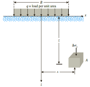
Refer to Figure 10.43. A strip load of q = 1450 lb/ft2 is applied over a width with B = 48 ft. Determine the increase in vertical stress at point A located z = 21 ft below the surface. Given x = 28.8 ft.

Figure 10.43
Expert Solution & Answer
Trending nowThis is a popular solution!

Students have asked these similar questions
Need help!! in this martin luther king jr. day is a non working day
The plan and 3D elevation of an earth retaining structure used for support excavation is shown in Figs. 3 and 4 respectively. The retaining structure is made of wood planks supported in the horizontal direction on vertical steel piles (HP sections). The HP piles shape of an H and are typically used for piles. The section properties of these sections (A, I, S, etc…) are given in Part 1 of the AISC steel manual. The spacing of the supporting HP piles is 20ft. The height of the piles is 15 from top of the pile to top of the footing. The height of the water table from the top of the footing is 9 ft as shown in the elevation in Fig. 4. The pile height and soil properties and the earth pressure distribution behind the retaining structure are shown in Fig. 5. Figs. 6 shows the equations for earth pressure. q is a live load surcharge that accounts for traffic on top of the embankment; q is typically assumed to be 250 psf (per the bridge code (AASHTO)). Use Fy = 50 ksi 1. Determine…
find SFD and BMD? where at node K the load is 25 kip
Chapter 10 Solutions
Principles of Geotechnical Engineering (MindTap Course List)
Ch. 10 - Prob. 10.1PCh. 10 - Prob. 10.2PCh. 10 - Prob. 10.3PCh. 10 - Prob. 10.4PCh. 10 - Prob. 10.5PCh. 10 - Prob. 10.6PCh. 10 - Point loads of magnitude 125, 250, and 500 kN act...Ch. 10 - Refer to Figure 10.41. Determine the vertical...Ch. 10 - For the same line loads given in Problem 10.8,...Ch. 10 - Refer to Figure 10.41. Given: q2 = 3800 lb/ft, x1...
Ch. 10 - Refer to Figure 10.42. Due to application of line...Ch. 10 - Refer to Figure 10.43. A strip load of q = 1450...Ch. 10 - Repeat Problem 10.12 for q = 700 kN/m2, B = 8 m,...Ch. 10 - Prob. 10.14PCh. 10 - For the embankment shown in Figure 10.45,...Ch. 10 - Refer to Figure 10.46. A flexible circular area of...Ch. 10 - Refer to Figure 10.47. A flexible rectangular area...Ch. 10 - Refer to the flexible loaded rectangular area...Ch. 10 - Prob. 10.19PCh. 10 - Prob. 10.20PCh. 10 - Refer to Figure 10.48. If R = 4 m and hw = height...Ch. 10 - Refer to Figure 10.49. For the linearly increasing...Ch. 10 - EB and FG are two planes inside a soil element...Ch. 10 - A soil element beneath a pave ment experiences...
Knowledge Booster
Learn more about
Need a deep-dive on the concept behind this application? Look no further. Learn more about this topic, civil-engineering and related others by exploring similar questions and additional content below.Similar questions
- find SFD and BMDarrow_forwardNote: Please provide a clear, step-by-step, simplified handwritten working out (no explanations!), ensuring it is completed without any AI involvement. I require an expert-level answer and will assess and rate your work based on its quality and accuracy, refer to the provided image for additional clarity. Make sure to double-check everything for correctness before submitting. Thanks, appreciate your time and effort!.arrow_forwardNeed help!! Add martin luther king jr day as a holiday so it won't be a work dayarrow_forward
- ضهقعفكضكشتبتلتيزذظظؤوروىووؤءظكصحبت٢٨٩٤٨٤ع٣خ٩@@@#&#)@)arrow_forwardA steel rod 100 ft long holds a 200 lb weight as shown. If the diameter of the circular rod is ¼ inch, find the maximum normal stress in the road, taking into account the weight of the rod itself. Use: density of steel = ϒ = 490 lb/ft3 .arrow_forwardضهقعفكضكشتبتلتيزذظظؤوروىووؤءظكصحبت٢٨٩٤٨٤ع٣خ٩@@@#&#)@)arrow_forward
- ضهقعفكضكشتبتلتيزذظظؤوروىووؤءظكصحبت٢٨٩٤٨٤ع٣خ٩@@@#&#)@)arrow_forwardA square flexible foundation of width B applies a uniform pressure go to the underlying ground. (a) Determine the vertical stress increase at a depth of 0.5B below the center using Aσ beneath the corner of a uniform rectangular load given by Aσ Variation of Influence Value I m n 0.5 0.6 0.8 1.0 0.2 0.4 0.2 0.01790 0.03280 0.03866 0.04348 0.05042 0.05471 0.4 0.03280 0.06024 0.07111 0.08009 0.09314 0.10129 0.5 0.03866 0.07111 0.08403 0.09473 0.11035 0.12018 0.6 0.04348 0.08009 0.09473 0.10688 0.12474 0.13605 0.8 0.05042 0.09314 0.11035 0.12474 0.14607 0.15978 1.0 0.05471 0.10129 0.12018 0.13605 0.15978 0.17522 (Enter your answer to three significant figures.) Ασ/90 = Activity Frame (b) Determine the vertical stress increase at a depth of 0.5B below the center using the 2 : 1 method equation below. 90 x B x L Aσ = (B+ z) (L+ z) (Enter your answer to three significant figures.) Δσ/90 = (c) Determine the vertical stress increase at a depth of 0.5B below the center using stress isobars in…arrow_forwardNeed help!!!arrow_forward
- 2 A flexible circular area is subjected to a uniformly distributed load of 450 kN/m² (the figure below). The diameter of the load area is 2 m. Estimate the average stress increase (Aσay) below the center of the loaded area between depths of 3 m and 6 m. H₂ 1.0 H₂ B 0.8 CHI HD DV 0.6 C 1.0 1.5 0.4 0.2 6.0 8.0. 10.0 2.0 2.5 3.0 4.0 5.0 H₁ (Enter your answer to two significant figures.) Δσαν τ kN/m² 6arrow_forwardRefer to the figure below. Using the procedure outlined in your textbook, determine the average stress increase in the clay layer below the center of the foundation due to the net foundation load of 45 tons. Use the equations: Aσ = and qo x B x L (B+ z)(L+ z) Aσ av (H2/H₁) Δσι +44 + Δσο net load 6 4:5 ft 10 ft 5ft x 5ft Sand Sand y=100 lb/ft³ Ysat 122 lb/ft³:" Ysat 120 lb/ft³: 0.7 C=0.25 Groundwater table C=0.06 Preconsolidation pressure = 2000 lb/ft² (Enter your answer to three significant figures.) Ασαν = lb/ft²arrow_forwardRefer to the figure below, which shows a flexible rectangular area. Given: B₁ = 4 ft, B₂ = 6 ft, L₁ = 8 ft, and L2 = 10 ft. If the area is subjected to a uniform load of 4100 lb/ft², determine the stress increase at a depth of 10 ft located immediately below point O. Use the table below. T B(1) 3 B(2) 2 L(1) * 4 L2) Table 1 Variation of Influence Value I n m 0.8 0.9 1.0 1.2 1.4 0.1 0.02576 0.02698 0.02794 0.02926 0.03007 0.2 0.05042 0.05283 0.05471 0.05733 0.05894 0.3 0.07308 0.07661 0.07938 0.08323 0.08561 0.4 0.09314 0.09770 0.10129 0.10631 0.10941 0.5 0.11035 0.11584 0.12018 0.12626 0.13003 0.6 0.12474 0.13105 0.13605 0.14309 0.14749 0.7 0.13653 0.14356 0.14914 0.15703 0.16199 0.8 0.14607 0.15371 0.15978 0.16843 0.17389 0.9 0.15371 0.16185 0.16835 0.1766 0.18357 1.0 0.15978 0.16835 0.17522 0.18508 0.19139 1.1 0.16843 0.17766 0.18508 0.19584 0.20278 (Enter your answer to three significant figures.) Aσ = lb/ft²arrow_forward
arrow_back_ios
SEE MORE QUESTIONS
arrow_forward_ios
Recommended textbooks for you
 Principles of Geotechnical Engineering (MindTap C...Civil EngineeringISBN:9781305970939Author:Braja M. Das, Khaled SobhanPublisher:Cengage Learning
 Principles of Foundation Engineering (MindTap Cou...Civil EngineeringISBN:9781305081550Author:Braja M. DasPublisher:Cengage Learning
 Fundamentals of Geotechnical Engineering (MindTap...Civil EngineeringISBN:9781305635180Author:Braja M. Das, Nagaratnam SivakuganPublisher:Cengage Learning
 Principles of Foundation Engineering (MindTap Cou...Civil EngineeringISBN:9781337705028Author:Braja M. Das, Nagaratnam SivakuganPublisher:Cengage Learning

Principles of Geotechnical Engineering (MindTap C...
Civil Engineering
ISBN:9781305970939
Author:Braja M. Das, Khaled Sobhan
Publisher:Cengage Learning

Principles of Foundation Engineering (MindTap Cou...
Civil Engineering
ISBN:9781305081550
Author:Braja M. Das
Publisher:Cengage Learning

Fundamentals of Geotechnical Engineering (MindTap...
Civil Engineering
ISBN:9781305635180
Author:Braja M. Das, Nagaratnam Sivakugan
Publisher:Cengage Learning

Principles of Foundation Engineering (MindTap Cou...
Civil Engineering
ISBN:9781337705028
Author:Braja M. Das, Nagaratnam Sivakugan
Publisher:Cengage Learning
Stress Distribution in Soils GATE 2019 Civil | Boussinesq, Westergaard Theory; Author: Gradeup- GATE, ESE, PSUs Exam Preparation;https://www.youtube.com/watch?v=6e7yIx2VxI0;License: Standard YouTube License, CC-BY