
MECHANICS OF MATERIALS
11th Edition
ISBN: 9780137605521
Author: HIBBELER
Publisher: RENT PEARS
expand_more
expand_more
format_list_bulleted
Videos
Textbook Question
thumb_up100%
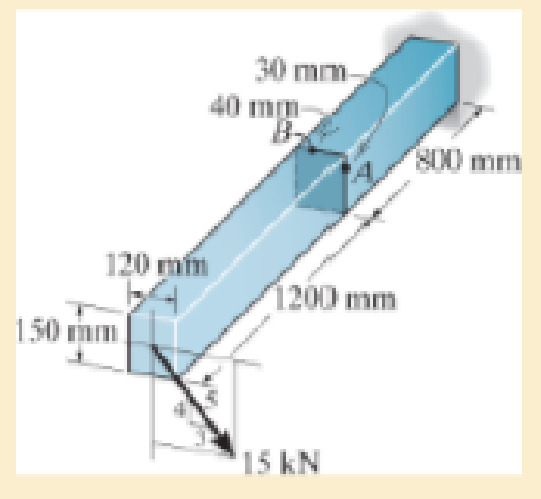
Chapter 9.3, Problem 34P
Determine the principal stresses in the cantilevered beam at points A and B.
Expert Solution & Answer
Want to see the full answer?
Check out a sample textbook solution
Students have asked these similar questions
6.76 A wind turbine is operating in a 12 m/s wind that has a den-
sity of 1.2 kg/m³. The diameter of the turbine silhouette is 4 m.
The constant-pressure (atmospheric) streamline has a diameter
of 3 m upstream of the windmill and 4.5 m downstream. Assume
that the velocity distributions are uniform and the air is incom-
pressible. Determine the force on the wind turbine.
m
P = Patm
4
Vz
4m
4 m
Fx.
Problem 6.76
For the position shown in the figure the spring is unstretched. The spring constant k, is designed such that after the system is released from rest, the speed of the mass is zero just as the 0.6 slug mass touches the floor. Find the spring constant, k and the maximum speed of block A and the location (distance above floor) where this occurs.
||!
Sign in
MMB241 - Tutorial L9.pd X PDF MMB241 - Tutorial L10.pX DE MMB241 - Tutorial L11.p x PDF Lecture W12 - Work and X
File C:/Users/KHULEKANI/Desktop/mmb241/MMB241%20-%20Tutorial%20L11.pdf
PDE Lecture W11 - Power and X
Draw
Alla | Ask Copilot
++
3
of 3
| D
6. If the 50-kg load A is hoisted by motor M so that the load has a constant velocity of 1.5
m/s, determine the power input to the motor, which operates at an efficiency € = 0.8.
1.5 m/s
2
7. The sports car has a mass of 2.3 Mg, and while it is traveling at 28 m/s the driver causes
it to accelerate at 5m/s². If the drag resistance on the car due to the wind is FD= 0.3v²N,
where v is the velocity in m/s, determine the power supplied to the engine at this instant.
The engine has a running efficiency of P = 0.68.
8. If the jet on the dragster supplies a constant thrust of T-20 kN, determine the power
generated by the jet as a function of time. Neglect drag and rolling resistance, and the loss
of fuel. The dragster has a mass of 1…
Chapter 9 Solutions
MECHANICS OF MATERIALS
Ch. 9.3 - Determine the normal stress and shear stress...Ch. 9.3 - Determine the equivalent state of stress on an...Ch. 9.3 - Also, find the corresponding orientation of the...Ch. 9.3 - Determine the equivalent state of stress on an...Ch. 9.3 - Determine the maximum principal stress at point B.Ch. 9.3 - Determine the principal stress at point C.Ch. 9.3 - Determine the stress components acting on the...Ch. 9.3 - Solve Prob.99 using the stress transformation...Ch. 9.3 - Determine the stress components acting on the...Ch. 9.3 - Determine the equivalent state of stress on an...
Ch. 9.3 - The stress along two planes at a point is...Ch. 9.3 - The state of stress at a point in a member is...Ch. 9.3 - The wood beam is subjected to a load of 12 kN. If...Ch. 9.3 - The internal loadings at a section of the beam are...Ch. 9.3 - Solve Prob.925 for point B. 925. The internal...Ch. 9.3 - Solve Prob.925 for point C. 925. The internal...Ch. 9.3 - It is subjected to a torque of 12 kip in. and a...Ch. 9.3 - A paper tube is formed by rolling a cardboard...Ch. 9.3 - Solve Prob.931 for the normal stress acting...Ch. 9.3 - Determine the principal stresses in the...Ch. 9.3 - The shaft has a diameter d and is subjected to the...Ch. 9.4 - Use Mohrs circle to determine the normal stress...Ch. 9.4 - Also, find the corresponding orientation of the...Ch. 9.4 - Draw Mohrs circle and determine the principal...Ch. 9.4 - Determine the principal stresses at a point on the...Ch. 9.4 - Determine the principal stresses at point A on the...Ch. 9.4 - Point A is just below the flange.Ch. 9.4 - Mohrs circle for the state of stress is shown in...Ch. 9.4 - Determine (a) the principal stresses and (b) the...Ch. 9.4 - Determine the equivalent state of stress if an...Ch. 9.4 - Draw Mohrs circle that describes each of the...Ch. 9.4 - Draw Mohrs circle trial describes each of the...Ch. 9.4 - Determine (a) the principal stresses and (b) the...Ch. 9.4 - Determine (a) the principal stresses and (b) the...Ch. 9.4 - Draw Mohrs circle that describes each of the...Ch. 9.4 - The grains of wood in the board make an angle of...Ch. 9.4 - A spherical pressure vessel has an inner radius of...Ch. 9.4 - The cylindrical pressure vessel has an inner...Ch. 9.4 - If the box wrench is subjected to the 50 lb force,...Ch. 9.4 - If the box wrench is subjected to the 50-lb force,...Ch. 9.5 - Draw the three Mohrs circles that describe each of...Ch. 9.5 - Draw the three Mohrs circles that describe the...Ch. 9.5 - Determine the principal stresses and the absolute...Ch. 9.5 - The solid shaft is subjected to a torque, bending...Ch. 9.5 - The frame is subjected to a horizontal force and...Ch. 9 - Prob. 1RPCh. 9 - The steel pipe has an inner diameter of 2.75 in....Ch. 9 - Determine the equivalent state of stress If an...Ch. 9 - The crane is used to support the 350-lb load....Ch. 9 - Determine the equivalent state of stress on an...Ch. 9 - The propeller shaft of the tugboat is subjected to...Ch. 9 - Determine the principal stresses in the box beam...Ch. 9 - Determine (a) the principal stresses and (b) the...Ch. 9 - Determine the stress components acting on the...
Knowledge Booster


Learn more about
Need a deep-dive on the concept behind this application? Look no further. Learn more about this topic, mechanical-engineering and related others by exploring similar questions and additional content below.Similar questions
- Q | Sign in PDE Lecture W09.pdf PDF MMB241 - Tutorial L9.pdi X PDF MMB241 - Tutorial L10.p X PDF MMB241 - Tutorial L11.p X Lecture W12-Work and X + File C:/Users/KHULEKANI/Desktop/mmb241/Lecture%20W12%20-%20Work%20and%20Energy.pdf ||! Draw | IA | a | Ask Copilot Class Work + 33 of 34 D Question 1 The engine of a 3500-N car is generating a constant power of 50 hp (horsepower) while the car is traveling up the slope with a constant speed. If the engine is operating with an efficiency of € 0.8, determine the speed of the car. Neglect drag and rolling resistance. Use g 9.81 m/s² and 1 hp = 745.7 W. 10 го Question 2 A man pushes on a 60-N crate with a force F. The force is always directed downward at an angle of 30° from the horizontal, as shown in the figure. The magnitude of the force is gradually increased until the crate begins to slide. Determine the crate's initial acceleration once it starts to move. Assume the coefficient of static friction is μ = 0.6, the coefficient of kinetic…arrow_forwardstate is Derive an expression for the volume expansivity of a substance whose equation of RT P = v-b a v(v + b)TZ where a and b are empirical constants.arrow_forwardFor a gas whose equation of state is P(v-b)=RT, the specified heat difference Cp-Cv is equal to which of the following (show all work): (a) R (b) R-b (c) R+b (d) 0 (e) R(1+v/b)arrow_forward
- of state is Derive an expression for the specific heat difference of a substance whose equation RT P = v-b a v(v + b)TZ where a and b are empirical constants.arrow_forwardTemperature may alternatively be defined as T = ди v Prove that this definition reduces the net entropy change of two constant-volume systems filled with simple compressible substances to zero as the two systems approach thermal equilibrium.arrow_forwardUsing the Maxwell relations, determine a relation for equation of state is (P-a/v²) (v−b) = RT. Os for a gas whose av Tarrow_forward
- (◉ Homework#8arrow_forwardHomework#8arrow_forwardBox A has a mass of 15 kilograms and is attached to the 20 kilogram Box B using the cord and pulley system shown. The coefficient of kinetic friction between the boxes and surface is 0.2 and the moment of inertia of the pulley is 0.5 kg * m^ 2. After 2 seconds, how far do the boxes move? A бро Barrow_forwardBox A has a mass of 15 kilograms and is attached to the 20 kilogram Box B using the cord and pulley system shown. The coefficient of kinetic friction between the boxes and surface is 0.2 and the moment of inertia of the pulley is 0.5 kg * m^2. Both boxes are 0.25 m long and 0.25 m high. The cord is attached to the bottom of Box A and the middle of box B. After 2 seconds, how far do the boxes move? A From бро Barrow_forwardarrow_back_iosSEE MORE QUESTIONSarrow_forward_iosRecommended textbooks for you
 Elements Of ElectromagneticsMechanical EngineeringISBN:9780190698614Author:Sadiku, Matthew N. O.Publisher:Oxford University Press
 Mechanics of Materials (10th Edition)Mechanical EngineeringISBN:9780134319650Author:Russell C. HibbelerPublisher:PEARSON
 Thermodynamics: An Engineering ApproachMechanical EngineeringISBN:9781259822674Author:Yunus A. Cengel Dr., Michael A. BolesPublisher:McGraw-Hill Education
 Control Systems EngineeringMechanical EngineeringISBN:9781118170519Author:Norman S. NisePublisher:WILEY
 Mechanics of Materials (MindTap Course List)Mechanical EngineeringISBN:9781337093347Author:Barry J. Goodno, James M. GerePublisher:Cengage Learning
 Engineering Mechanics: StaticsMechanical EngineeringISBN:9781118807330Author:James L. Meriam, L. G. Kraige, J. N. BoltonPublisher:WILEY
Elements Of ElectromagneticsMechanical EngineeringISBN:9780190698614Author:Sadiku, Matthew N. O.Publisher:Oxford University PressMechanics of Materials (10th Edition)Mechanical EngineeringISBN:9780134319650Author:Russell C. HibbelerPublisher:PEARSONThermodynamics: An Engineering ApproachMechanical EngineeringISBN:9781259822674Author:Yunus A. Cengel Dr., Michael A. BolesPublisher:McGraw-Hill EducationControl Systems EngineeringMechanical EngineeringISBN:9781118170519Author:Norman S. NisePublisher:WILEYMechanics of Materials (MindTap Course List)Mechanical EngineeringISBN:9781337093347Author:Barry J. Goodno, James M. GerePublisher:Cengage LearningEngineering Mechanics: StaticsMechanical EngineeringISBN:9781118807330Author:James L. Meriam, L. G. Kraige, J. N. BoltonPublisher:WILEY
Mechanics of Materials Lecture: Beam Design; Author: UWMC Engineering;https://www.youtube.com/watch?v=-wVs5pvQPm4;License: Standard Youtube License