
MECHANICS OF MATERIALS
11th Edition
ISBN: 9780137605521
Author: HIBBELER
Publisher: RENT PEARS
expand_more
expand_more
format_list_bulleted
Concept explainers
Videos
Textbook Question
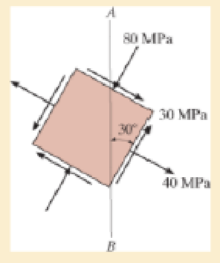
Chapter 9.3, Problem 10P
Solve Prob.9–9 using the stress transformation equation developed in Sec.9.2.
Expert Solution & Answer
Want to see the full answer?
Check out a sample textbook solution
Students have asked these similar questions
A group of 23 power transistors, dissipating 2 W each, are to be cooled by attaching them to a black-anodized square aluminum plate and mounting the plate on the wall of a room at 30°C. The emissivity of the transistor and the plate surfaces is 0.9. Assuming the heat transfer from the back side of the plate to be negligible and the temperature of the surrounding surfaces to be the same as the air temperature of the room, determine the length of the square plate if the average surface temperature of the plate is not to exceed 50°C. Start the iteration process with an initial guess of the size of the plate as 43 cm.
The properties of air at 1 atm and the film temperature of (Ts + T)/2 = (50 + 30)/2 = 40°C are k = 0.02662 W/m·°C, ν = 1.702 × 10⁻⁵ m2 /s, Pr = 0.7255, and β = 0.003195 K–1.
Multiple Choice
0.473 m
0.284 m
0.513 m
0.671 m
A 40-cm-diameter, 127-cm-high cylindrical hot water tank is located in the bathroom of a house maintained at 20°C. The surface
temperature of the tank is measured to be 44°C and its emissivity is 0.4. Taking the surrounding surface temperature to be also 20°C,
determine the rate of heat loss from all surfaces of the tank by natural convection and radiation.
The properties of air at 32°C are k=0.02603 W/m-K, v=1.627 x 10⁻⁵ m²/s, Pr = 0.7276, and ẞ = 0.003279 K-1
The rate of heat loss from all surfaces of the tank by natural convection is
The rate of heat loss from all surfaces of the tank by radiation is
W.
W.
A 2.5-m-long thin vertical plate is subjected to uniform heat flux on one side, while the other side is exposed to cool air at 5°C. The
plate surface has an emissivity of 0.73, and its midpoint temperature is 55°C. Determine the heat flux subjected on the plate surface.
Uniform
heat flux
-Plate, € = 0.73
Cool air
5°C
7
TSUIT
Given: The properties of water at Tf,c= 30°C.
k=0.02588 W/m.K,
v=1.608 x 10⁻⁵ m²/s
Pr = 0.7282
The heat flux subjected on the plate surface is
W/m²
Chapter 9 Solutions
MECHANICS OF MATERIALS
Ch. 9.3 - Determine the normal stress and shear stress...Ch. 9.3 - Determine the equivalent state of stress on an...Ch. 9.3 - Also, find the corresponding orientation of the...Ch. 9.3 - Determine the equivalent state of stress on an...Ch. 9.3 - Determine the maximum principal stress at point B.Ch. 9.3 - Determine the principal stress at point C.Ch. 9.3 - Determine the stress components acting on the...Ch. 9.3 - Solve Prob.99 using the stress transformation...Ch. 9.3 - Determine the stress components acting on the...Ch. 9.3 - Determine the equivalent state of stress on an...
Ch. 9.3 - The stress along two planes at a point is...Ch. 9.3 - The state of stress at a point in a member is...Ch. 9.3 - The wood beam is subjected to a load of 12 kN. If...Ch. 9.3 - The internal loadings at a section of the beam are...Ch. 9.3 - Solve Prob.925 for point B. 925. The internal...Ch. 9.3 - Solve Prob.925 for point C. 925. The internal...Ch. 9.3 - It is subjected to a torque of 12 kip in. and a...Ch. 9.3 - A paper tube is formed by rolling a cardboard...Ch. 9.3 - Solve Prob.931 for the normal stress acting...Ch. 9.3 - Determine the principal stresses in the...Ch. 9.3 - The shaft has a diameter d and is subjected to the...Ch. 9.4 - Use Mohrs circle to determine the normal stress...Ch. 9.4 - Also, find the corresponding orientation of the...Ch. 9.4 - Draw Mohrs circle and determine the principal...Ch. 9.4 - Determine the principal stresses at a point on the...Ch. 9.4 - Determine the principal stresses at point A on the...Ch. 9.4 - Point A is just below the flange.Ch. 9.4 - Mohrs circle for the state of stress is shown in...Ch. 9.4 - Determine (a) the principal stresses and (b) the...Ch. 9.4 - Determine the equivalent state of stress if an...Ch. 9.4 - Draw Mohrs circle that describes each of the...Ch. 9.4 - Draw Mohrs circle trial describes each of the...Ch. 9.4 - Determine (a) the principal stresses and (b) the...Ch. 9.4 - Determine (a) the principal stresses and (b) the...Ch. 9.4 - Draw Mohrs circle that describes each of the...Ch. 9.4 - The grains of wood in the board make an angle of...Ch. 9.4 - A spherical pressure vessel has an inner radius of...Ch. 9.4 - The cylindrical pressure vessel has an inner...Ch. 9.4 - If the box wrench is subjected to the 50 lb force,...Ch. 9.4 - If the box wrench is subjected to the 50-lb force,...Ch. 9.5 - Draw the three Mohrs circles that describe each of...Ch. 9.5 - Draw the three Mohrs circles that describe the...Ch. 9.5 - Determine the principal stresses and the absolute...Ch. 9.5 - The solid shaft is subjected to a torque, bending...Ch. 9.5 - The frame is subjected to a horizontal force and...Ch. 9 - Prob. 1RPCh. 9 - The steel pipe has an inner diameter of 2.75 in....Ch. 9 - Determine the equivalent state of stress If an...Ch. 9 - The crane is used to support the 350-lb load....Ch. 9 - Determine the equivalent state of stress on an...Ch. 9 - The propeller shaft of the tugboat is subjected to...Ch. 9 - Determine the principal stresses in the box beam...Ch. 9 - Determine (a) the principal stresses and (b) the...Ch. 9 - Determine the stress components acting on the...
Knowledge Booster


Learn more about
Need a deep-dive on the concept behind this application? Look no further. Learn more about this topic, mechanical-engineering and related others by exploring similar questions and additional content below.Similar questions
- Hot water is flowing at an average velocity of 5.82 ft/s through a cast iron pipe (k=30 Btu/h-ft-°F) whose inner and outer diameters are 1.0 in and 1.2 in, respectively. The pipe passes through a 50-ft-long section of a basement whose temperature is 60°F. The emissivity of the outer surface of the pipe is 0.5, and the walls of the basement are also at about 60°F. If the inlet temperature of the water is 150°F and the heat transfer coefficient on the inner surface of the pipe is 30 Btu/h-ft².°F, determine the temperature drop of water as it passes through the basement. Evaluate air properties at a film temperature of 105°C and 1 atm pressure. The properties of air at 1 atm and the film temperature of (Ts+ T∞)/2 = (150+60)/2 = 105°F are k=0.01541 Btu/h-ft-°F. v=0.1838 × 10⁻³ ft2/s, Pr = 0.7253, and ẞ = 0.00177R-1arrow_forwardhand-written solutions only, please. correct answers upvoted!arrow_forwardhand-written solutions only, please. correct answers upvoted!arrow_forward
- ! Required information Consider a flat-plate solar collector placed horizontally on the flat roof of a house. The collector is 1.3 m wide and 2.8 m long, and the average temperature of the exposed surface of the collector is 42°C. The properties of air at 1 atm and the film temperature are k=0.02551 W/m-°C, v = 1.562 × 10⁻⁵ m²/s, Pr = 0.7286, and ẞ= 0.003356 K-1 Determine the rate of heat loss from the collector by natural convection during a calm day when the ambient air temperature is 8°C. The rate of heat loss from the collector by natural convection is W.arrow_forwardhand-written solutions only, please. correct answers upvoted!arrow_forwardhand-written solutions only, please. correct answers upvoted!arrow_forward
- Please find the torsional yield strength, the yield strength, the spring index, and the mean diameter.arrow_forward(read image) (Answer Given)arrow_forward6.76 A wind turbine is operating in a 12 m/s wind that has a den- sity of 1.2 kg/m³. The diameter of the turbine silhouette is 4 m. The constant-pressure (atmospheric) streamline has a diameter of 3 m upstream of the windmill and 4.5 m downstream. Assume that the velocity distributions are uniform and the air is incom- pressible. Determine the force on the wind turbine. m P = Patm 4 Vz 4m 4 m Fx. Problem 6.76arrow_forward
arrow_back_ios
SEE MORE QUESTIONS
arrow_forward_ios
Recommended textbooks for you
 Mechanics of Materials (MindTap Course List)Mechanical EngineeringISBN:9781337093347Author:Barry J. Goodno, James M. GerePublisher:Cengage Learning
Mechanics of Materials (MindTap Course List)
Mechanical Engineering
ISBN:9781337093347
Author:Barry J. Goodno, James M. Gere
Publisher:Cengage Learning
Understanding Stress Transformation and Mohr's Circle; Author: The Efficient Engineer;https://www.youtube.com/watch?v=_DH3546mSCM;License: Standard youtube license