
Concept explainers
Videos
The principal stresses at any point located on the surface of the shaft.
Answer to Problem 9.89RP
The principal stresses at any point located on the surface of the shaft are
Explanation of Solution
Given information:
Rotation of the propeller is
The engine develops the power of 900 kW.
Thrust on the shaft is
The outer diameter of the shaft is 250 mm.
Calculation:
Find the power transmission as shown below.
Here, P is the power transmission and
Substitute 900 kW for P and
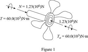
Sketch the internal torque and forces for the propeller shaft as shown in Figure 1.
Find the section properties as shown below.
Find the cross sectional area as shown below.

Here, d is the diameter of the shaft.
Substitute 250 mm for d.
Find the polar moment of inertia as shown below.
Substitute 250 mm for d.
Find the normal stress as shown below.
Here, N is the normal force and A is the cross sectional area.
Substitute
Convert the unit from
Find the shear stress as shown below.
Here, T is the torque, J is the polar moment of inertia, and c is the centroidal distance between the neutral axis and the extreme fibre.
Substitute
Convert the unit from
Sketch the state of stress as shown in Figure 2.
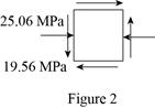
Refer to Figure 2.
Find the in-plane principal stresses as shown below.
Here,
Substitute
The principal stresses are,
Therefore, the principal stresses at any point located on the surface of the shaft are
Want to see more full solutions like this?
Chapter 9 Solutions
Mechanics of Materials


- 6: Refer to the figure.Given: W1 = 200 kN/m; W2 = 300 kN/m; L1 = 2 m; L2 = 3 m; L3 = 2 m(a) Calculate the total length L so that the resulting upward pressureq is uniform. (b) draw the shear and moment diagram and determinethe maximum shear, maximum positive and negative bendingmoments.arrow_forwardA six cylinder, four-stroke diesel engine develops a power of 200 kW at 2000 rpm. The bsfc is 0.2 kW/kg h of fuel with 34.9° API. The fuel is injected at an average pressure of 350 bar and the pressure in the combustion chamber is 40 bar. Assuming Ca for injector 0.75 and the atmospheric pressure 1 bar. Determine the period of injection in seconds if the total orifice area required per injector is 0.4876 × 10⁻⁶ m².arrow_forwardTrieed a detailed drawing Win explanatio LL Antsmi 1981x pu + 96252 اه 6. The Pre-combustion chamber design engines employ nozzle type commonly referred to as a ....... a. inward-opening nozzle b. multiple-hole nozzle. c. pintle nozzle. d. none of these. 7. If the temperature of the spark plug tip is less than 350 °C, ......... a. the plug might not work. b. the carbon deposits would increase. 8. Port injection sprays fuel....... c. pre-ignition will occur. d. none of these. a. towards the intake valve. b. in the engine cylinder. c. in the throttle body assembly. d. none of these. 9. When the fuel-air mixture changed from best power to a richer ratio, the spark advance should be........ a. increased. b. decreased. c. left unchanged. d. none of these. d. none of these. 10. Spark plugs are classified as hot plugs and cold plugs depending upon ........ a. spark gap. b. the type of plug c. the operating temperature insulator. range of the electrode tip. ---20125 750 x2.01 SP 5.arrow_forward
- A 1. How does the octane number (O.N.) of the fuel a. Higher ignition advance is required for a high O.N. fuel. b. Higher ignition retard is required for a high O.N. fuel. affect spark ing:d. Nou does not affect spark timing. c. The octane number 2. How does the ignition system account for load change? these. of a. The throttle b. The vacuum ignition governor c. The mechanism of d. None of is wide opened. provide additional spark advance at part throttle positions. centrifugal advance does the job. these. 3. In the common rail fuel system the fuel is metered by ........ a. low pressure pump. b. injectors. c. high pressure pump. d. none of these. 4.......... is the time period, measured in degrees of cam rotation, during which the contact points remain closed between each opening. a. Distributor. b. Dwell. c. ECU. d. none of these. 5. The trigger wheel in TCI system replaces the ......... used in a contact breaker distributor. a. pickup coil. b. distributor cam. c. condenser. 750 x2.01…arrow_forwarda い يكا 4 +91- pu Answer the following statements by true or false, giving the reason for your answer: 1. Injection pressure in CI engines should be sufficiently high. 2. The purpose of the condenser in battery ignition system is to prevent spark in the ignition coil assembly. 3. An idling engine requires lean mixture of fuel and air. 4. Factors which decide optimum engine firing order are engine vibration, engine cooling and back pressure. 5. It is the duty of the header to control over speeding during CI engine operation when drastic reduction in load occurs. ---20125 750 x2.01 SParrow_forward6. The Pre-combustion chamber design engines employ nozzle type commonly referred to as a a. inward-opening nozzle b. multiple-hole nozzle. c. pintle nozzle. d. none of these. 7. If the temperature of the spark plug tip is less than 350 °C, ........ a. the plug might b. the carbon deposits not work. would increase. c. pre-ignition will occur. d. none of these. 8. Port injection sprays fuel........ a. towards the intake valve. b. in the engine cylinder. c. in the throttle body d. none of assembly. these. 9. When the fuel-air mixture changed from best power to a richer ratio, the spark advance should be ........ a. increased. b. decreased. c. left unchanged. d. none of these. 10. Spark plugs are classified as hot plugs and cold plugs depending upon a. spark gap. b. the type of plug c. the operating temperature d. none of these. range of the electrode tip. insulator.arrow_forward
- 1: A H = 6 m cantilever retaining wall is subjected to a soil pressurelinearly varying from zero at the top to 90 kPa at the bottom. As an additionalsupport, it is anchored at depth y = 2 m. with maximum tension equal to 25kN. Assume that the stem provides fully retrained support. Draw the shearand moment diagram of the wall to calculate the following: (a) Maximumpositive bending moment per linear meter; (b) maximum negative bendingmoment per linear meter; (c) maximum shear force per linear meter.arrow_forwardCORRECT AND DETAILED SOLUTION WITH COMPLETE FBD ONLY. I WILL UPVOTE. 9: The beam shown has a width of 80 mm and its allowable bending stress is not to exceed 120 MPa. Calculatethe required depth of the beam.arrow_forwardPROBLEM 4: A pre-stressed concrete pile of length L (m) is to be picked up by crane cables at two points, both equidistant from the ends. If the concrete pile has a cross-sectional area of A (m²) and concrete has unit weight of Yc (kN/m³), calculate the distance of the pick-up points from the end in terms of pile length. (Hint: to minimize the absolute maximum moment, the maximum negative and maximum negative moments should be equal)arrow_forward
 Elements Of ElectromagneticsMechanical EngineeringISBN:9780190698614Author:Sadiku, Matthew N. O.Publisher:Oxford University Press
 Mechanics of Materials (10th Edition)Mechanical EngineeringISBN:9780134319650Author:Russell C. HibbelerPublisher:PEARSON
 Thermodynamics: An Engineering ApproachMechanical EngineeringISBN:9781259822674Author:Yunus A. Cengel Dr., Michael A. BolesPublisher:McGraw-Hill Education
 Control Systems EngineeringMechanical EngineeringISBN:9781118170519Author:Norman S. NisePublisher:WILEY
 Mechanics of Materials (MindTap Course List)Mechanical EngineeringISBN:9781337093347Author:Barry J. Goodno, James M. GerePublisher:Cengage Learning
 Engineering Mechanics: StaticsMechanical EngineeringISBN:9781118807330Author:James L. Meriam, L. G. Kraige, J. N. BoltonPublisher:WILEY