
Mechanics of Materials
9th Edition
ISBN: 9780133254426
Author: Russell C. Hibbeler
Publisher: Prentice Hall
expand_more
expand_more
format_list_bulleted
Videos
Textbook Question
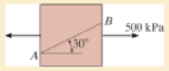
Chapter 9.3, Problem 9.1FP
Determine the normal stress and shear stress acting on the inclined plane AB. Sketch the result on the sectioned element.
Expert Solution & Answer
Want to see the full answer?
Check out a sample textbook solution
Students have asked these similar questions
CORRECT AND DETAILED HANDWRITTEN SOLUTION WITH FBD ONLY. I WILL UPVOTE THANK YOU. CORRECT ANSWER IS ALREADY PROVIDED.
20: A 2022 Porsche 911 (992) GT3 is crossing a 20 ft bridge. The specification of the car is shown below.Determine the maximum shear (in lb) and moment (in lb-ft) on the bridge.
ANS: Vmax = 2,680.850 lb ; Mmax = 11,233.13 lb-ft
CORRECT AND DETAILED HANDWRITTEN SOLUTION WITH FBD ONLY. I WILL UPVOTE THANK YOU. CORRECT ANSWER IS ALREADY PROVIDED.
Answers:
P1 = 208.625 KN/M
P2 = 281.310 KN/M
P = 15.491 KN/M
FB = 463.402 MPA
FV = 55.034 MPA
CORRECT AND DETAILED HANDWRITTEN SOLUTION WITH FBD ONLY. I WILL UPVOTE THANK YOU. CORRECT ANSWER IS ALREADY PROVIDED.
18: Determine the maximum shear and moment that would be experienced by a 10 m beam if a three-wheelmoving load of 10 kN, 30 kN, and 5 kN respectively will pass it by. The distance between the 1st and 2nd load is 1 m and the distance between the 2nd and 3rd load is 3 m.ANS: Vmax = 40 kN ; Mmax = 100.014 kN-m
Chapter 9 Solutions
Mechanics of Materials
Ch. 9.3 - In each case, the state of stress x, y, xy...Ch. 9.3 - Given the state of stress shown on the element,...Ch. 9.3 - Determine the normal stress and shear stress...Ch. 9.3 - Determine the equivalent state of stress on an...Ch. 9.3 - Also, find the corresponding orientation of the...Ch. 9.3 - Determine the equivalent state of stress on an...Ch. 9.3 - Determine the maximum principal stress at point B.Ch. 9.3 - Determine the principal stress at point C.Ch. 9.3 - Prove that the sum of the normal stresses x + y =...Ch. 9.3 - 9-2. The state of stress at a point in a member is...
Ch. 9.3 - Determine the stress components acting on the...Ch. 9.3 - Determine the normal stress and shear stress...Ch. 9.3 - Determine the normal stress and shear stress...Ch. 9.3 - 9-6. Determine the normal stress and shear stress...Ch. 9.3 - 9-7. Determine the normal stress and shear stress...Ch. 9.3 - *9-8. Determine the equivalent state of stress on...Ch. 9.3 - 9-9. Determine the equivalent state of stress on...Ch. 9.3 - Determine the equivalent state of stress on an...Ch. 9.3 - Determine the equivalent slate of stress on an...Ch. 9.3 - *9-12. Determine the equivalent state of stress on...Ch. 9.3 - 9-13. Determine the equivalent state of stress on...Ch. 9.3 - 9-14. The state of stress at a point is shown on...Ch. 9.3 - The state of stress at a point is shown on the...Ch. 9.3 - Determine the equivalent state of stress on an...Ch. 9.3 - Determine the equivalent state of stress on an...Ch. 9.3 - A point on a thin plate is subjected to the two...Ch. 9.3 - Determine the equivalent state of stress on an...Ch. 9.3 - *9-20. Planes AB and BC at a point are subjected...Ch. 9.3 - The stress acting on two planes at a point is...Ch. 9.3 - The grains of wood in the board make an angle of...Ch. 9.3 - The wood beam is subjected to a load of 12 kN. If...Ch. 9.3 - *9-24. The wood beam is subjected to a load of 12...Ch. 9.3 - 9-25. The wooden block will fail if the shear...Ch. 9.3 - 9-26. The bracket is subjected to the force of 3...Ch. 9.3 - 9-27. The bracket is subjected to the force of 3...Ch. 9.3 - 9-28. The 25-mm thick rectangular bar is subjected...Ch. 9.3 - 9-29. The 3-in. diameter shaft is supported by a...Ch. 9.3 - 9-30. The state of stress at a point in a member...Ch. 9.3 - 9-31. Determine the principal stress at point A on...Ch. 9.3 - 9-32. Determine the maximum in-plane shear stress...Ch. 9.3 - 9-33. The clamp bears down on the smooth surface...Ch. 9.3 - 9-34. Determine the principal stress and the...Ch. 9.3 - 9-35. The square steel plate has a thickness of 10...Ch. 9.3 - *9-36. The square steel plate has a thickness of...Ch. 9.3 - The shaft has a diameter d and is subjected to the...Ch. 9.3 - Prob. 9.38PCh. 9.3 - Prob. 9.39PCh. 9.3 - The wide-flange beam is subjected to the 50-kN...Ch. 9.3 - Solve Pro b. 9-40 for point B located on the web...Ch. 9.3 - Prob. 9.42PCh. 9.3 - Prob. 9.43PCh. 9.4 - Use Mohrs circle to determine the normal stress...Ch. 9.4 - Also, find the corresponding orientation of the...Ch. 9.4 - Draw Mohrs circle and determine the principal...Ch. 9.4 - Determine the principal stresses at a point on the...Ch. 9.4 - Determine the principal stresses at point A on the...Ch. 9.4 - Point A is just below the flange.Ch. 9.4 - Solve Prob.93 using Mohrs circle. 93. Determine...Ch. 9.4 - 9-45. Solve Prob. 9-6 using Mohr’s circle.
9-6....Ch. 9.4 - 9-46. Solve Prob. 9-14 using Mohr’s circle.
9-14....Ch. 9.4 - Solve Prob.911 using Mohrs circle. 911. Determine...Ch. 9.4 - *9-48. Solve Prob. 9-12 using Mohr’s...Ch. 9.4 - Solve Prob.916 using Mohrs circle. 916. Determine...Ch. 9.4 - Mohrs circle for the state of stress is shown in...Ch. 9.4 - Prob. 9.51PCh. 9.4 - Prob. 9.52PCh. 9.4 - 9-53. Determine the equivalent state of stress if...Ch. 9.4 - Prob. 9.54PCh. 9.4 - Prob. 9.55PCh. 9.4 - Prob. 9.56PCh. 9.4 - Determine (a) the principal stresses and (b) the...Ch. 9.4 - 9-58. Determine the equivalent state of stress if...Ch. 9.4 - Prob. 9.59PCh. 9.4 - Prob. 9.60PCh. 9.4 - 9-61. Draw Mohr’s circle that describes each of...Ch. 9.4 - The grains of wood in the board make an angle of...Ch. 9.4 - The post is fixed supported at its base and a...Ch. 9.4 - Determine the principal stresses, the maximum...Ch. 9.4 - The thin-walled pipe has an inner diameter of 0.5...Ch. 9.4 - 9-66. Determine the principal stress and maximum...Ch. 9.4 - Prob. 9.67PCh. 9.4 - The rotor shaft of the helicopter is subjected to...Ch. 9.4 - The pedal crank for a bicycle has the cross...Ch. 9.4 - A spherical pressure vessel has an inner radius of...Ch. 9.4 - The cylindrical pressure vessel has an inner...Ch. 9.4 - Determine the normal and shear stresses at point D...Ch. 9.4 - Determine the principal stress at point D, Which...Ch. 9.4 - If the box wrench is subjected to the 50 lb force,...Ch. 9.4 - If the box wrench is subjected to the 50-lb force,...Ch. 9.4 - Prob. 9.76PCh. 9.5 - Draw the three Mohrs circles that describe each of...Ch. 9.5 - Draw the three Mohrs circles that describe the...Ch. 9.5 - 9-79. The stress at a point is shown on the...Ch. 9.5 - Determine the principal stresses and the absolute...Ch. 9.5 - 9-81. The stress at a point is shown on the...Ch. 9.5 - Determine the principal stresses and the absolute...Ch. 9.5 - Determine the principal stresses and the absolute...Ch. 9.5 - Prob. 9.85PCh. 9.5 - Prob. 9.86PCh. 9.5 - 9-87. Determine the principal stresses and...Ch. 9.5 - *9.88. Determine the principal stresses and...Ch. 9 - Prob. 9.89RPCh. 9 - Prob. 9.90RPCh. 9 - Prob. 9.91RPCh. 9 - The steel pipe has an inner diameter of 2.75 in....Ch. 9 - Determine the equivalent state of stress If an...Ch. 9 - The crane is used to support the 350-lb load....Ch. 9 - Determine the equivalent state of stress on an...Ch. 9 - The propeller shaft of the tugboat is subjected to...Ch. 9 - Determine the principal stresses in the box beam...Ch. 9 - Determine (a) the principal stresses and (b) the...Ch. 9 - Determine the stress components acting on the...
Additional Engineering Textbook Solutions
Find more solutions based on key concepts
The following C++ program will not compile because the lines have been mixed up. cout Success\n; cout Success...
Starting Out with C++ from Control Structures to Objects (9th Edition)
1.2 Explain the difference between geodetic and plane
surveys,
Elementary Surveying: An Introduction To Geomatics (15th Edition)
How does a computers main memory differ from its auxiliary memory?
Java: An Introduction to Problem Solving and Programming (8th Edition)
How is the hydrodynamic entry length defined for flow in a pipe? Is the entry length longer in laminar or turbu...
Fluid Mechanics: Fundamentals and Applications
The ____________ is always transparent.
Web Development and Design Foundations with HTML5 (8th Edition)
What types of coolant are used in vehicles?
Automotive Technology: Principles, Diagnosis, And Service (6th Edition) (halderman Automotive Series)
Knowledge Booster


Learn more about
Need a deep-dive on the concept behind this application? Look no further. Learn more about this topic, mechanical-engineering and related others by exploring similar questions and additional content below.Similar questions
- CORRECT AND DETAILED HANDWRITTEN SOLUTION WITH FBD ONLY. I WILL UPVOTE THANK YOU. CORRECT ANSWER IS ALREADY PROVIDED. 5: A 12-m simply supported bridge is constructed with 100-mm concrete slab deck supported by precastconcrete stringers spaced 800 mm on center. Analyze the stringers when subjected to a moving load consisting of 3 evenly spaced axle loads at 3 m and equivalent to 20 kN, 30 kN and 40 kN respectively. The self-weight of the stringers is 8.5 kN/m and the concrete deck has a unit weight of 24 kN/m3 . Neglect all other superimposed loads. Calculate: (a) the maximum shear force in the stringers; (b) the maximum bending moment in the stringers. Answer: Vmax = 135.020 KN, Mmax = 477.388 KN-Marrow_forwardCORRECT AND DETAILED HANDWRITTEN SOLUTION WITH FBD ONLY. I WILL UPVOTE THANK YOU. CORRECT ANSWER IS ALREADY PROVIDED. 19: A 22-wheeler truck is crossing over 25 m bridge. The dimensions between the axles of the truck are shownin the figure below. Axles 1 to 3 carry a 90 kN load each, axles 4 and 5 carry a 65 kN load each, and the axle directly below the cab of the truck has a load of 100 kN. Determine the maximum shear and moment on the bridge.ANS: Vmax = 374.92 kN ; Mmax = 1,702.229 kN-marrow_forwardCORRECT AND DETAILED HANDWRITTEN SOLUTION WITH FBD ONLY. I WILL UPVOTE THANK YOU. CORRECT ANSWER IS ALREADY PROVIDED. 1. A H = 6 m cantilever retaining wall is subjected to a soil pressurelinearly varying from zero at the top to 90 kPa at the bottom. As an additionalsupport, it is anchored at depth y = 2 m. with maximum tension equal to 25kN. Assume that the stem provides fully retrained support. Draw the shearand moment diagram of the wall to calculate the following: (a) Maximumpositive bending moment per linear meter; (b) maximum negative bendingmoment per linear meter; (c) maximum shear force per linear meter. answer: +MMax = 440 kn-m, -Mmax = 0kn-M, Vmax = 245 KNarrow_forward
- CORRECT AND DETAILED HANDWRITTEN SOLUTION WITH FBD ONLY. I WILL UPVOTE THANK YOU. CORRECT ANSWER IS ALREADY PROVIDED. 17: A simply supported beam with the section shown below has an allowableflexural shearing stress of 43 MPa. (a) Determine the maximum allowable shearing force onthe section. And (b) what is the minimum thickness of plate that should be welded at theflanges if the section is to withstand a total shearing force of 200 kN. The additional plate willhave its base dimension equal to the flange dimension.ANS: V = 179.333 kN ; t = 23.181 mmarrow_forwardCORRECT AND DETAILED HANDWRITTEN SOLUTION WITH FBD ONLY. I WILL UPVOTE THANK YOU. CORRECT ANSWER IS ALREADY PROVIDED. Answer: A = 0.207 L(M)arrow_forwardQu 4 The 12-kg slender rod is attached to a spring, which has an unstretched length of 2 m. If the rod is released from rest when 0 = 30°, determine its angular velocity at the instant 0 = 90°. 2 m B k = 40 N/m 2 marrow_forward
- CORRECT AND DETAILED HANDWRITTEN SOLUTION WITH FBD ONLY. I WILL UPVOTE THANK YOU. CORRECT ANSWER IS ALREADY PROVIDED. 13: A cantilever beam is of length 1.5 m,loaded by a concentrated load P at its tip as shown inFig. 8-18(a), and is of circular cross section (R = 100 mm),having two symmetrically placed longitudinal holes asindicated. The material is titanium alloy, having anallowable working stress in bending of 600 MPa.Determine the maximum allowable value of the verticalforce P. ANS: P = 236,589.076 N = 236.589 kNarrow_forwardCORRECT AND DETAILED HANDWRITTEN SOLUTION WITH FBD ONLY. I WILL UPVOTE THANK YOU. CORRECT ANSWER IS ALREADY PROVIDED. 15: Consider a beam having an I-type cross section as shown in Fig. 8-45. Ashearing force V of 150 kN acts over the section. Determine the maximum and minimumvalues of the shearing stress in the vertical web of the section.ANS: fv(max) = 44.048 MPa ; fv(min) = 33.202 MPaarrow_forwardCORRECT AND DETAILED HANDWRITTEN SOLUTION WITH FBD ONLY. I WILL UPVOTE THANK YOU. CORRECT ANSWER IS ALREADY PROVIDED. 12: A steel cantilever beam 16 ft 8 in in length is subjected to a concentrated load of 320 lb acting at the freeend of the bar. A commercially available rolled steel section, designated as W12x32, is used for the beam. Assume that the total depth of the beam is 12 in, and the neutral axis of the section is in the middle. Determine the maximum tensile and compressive stresses. (Properties of commercially available rolled steel section provided in the table. Z = section modulus). ANS: σT = σC = 1,572.482 lb/in2arrow_forward
- CORRECT AND DETAILED HANDWRITTEN SOLUTION WITH FBD ONLY. I WILL UPVOTE THANK YOU. CORRECT ANSWER IS ALREADY PROVIDED. 14: Two ½-in x 8-in cover plates are welded to two channels 10 in high to formthe cross section of the beam shown in Fig. 8-59. Loads are in a vertical plane and bendingtakes place about a horizontal axis. The moment of inertia of each channel about ahorizontal axis through the centroid is 78.5 in4. If the maximum allowable elastic bendingstress is 18,000 lb/in2, determine the maximum bending moment that may be developedin the beam.ANS: 1,236,000 lb-in.arrow_forwardCORRECT AND DETAILED HANDWRITTEN SOLUTION WITH FBD ONLY. I WILL UPVOTE THANK YOU. CORRECT ANSWER IS ALREADY PROVIDED. 11: A beam of circular cross section is 7 in in diameter. It is simply supported at each end and loaded by twoconcentrated loads of 20,000 lb each, applied 12 in from the ends of the beam. Determine the maximum bending stressin the beam. ANS: σ = 7,127.172 lb/in2arrow_forwardusing the theorem of three moments, find all the reactions and supportsarrow_forward
arrow_back_ios
SEE MORE QUESTIONS
arrow_forward_ios
Recommended textbooks for you
 Elements Of ElectromagneticsMechanical EngineeringISBN:9780190698614Author:Sadiku, Matthew N. O.Publisher:Oxford University Press
 Mechanics of Materials (10th Edition)Mechanical EngineeringISBN:9780134319650Author:Russell C. HibbelerPublisher:PEARSON
 Thermodynamics: An Engineering ApproachMechanical EngineeringISBN:9781259822674Author:Yunus A. Cengel Dr., Michael A. BolesPublisher:McGraw-Hill Education
 Control Systems EngineeringMechanical EngineeringISBN:9781118170519Author:Norman S. NisePublisher:WILEY
 Mechanics of Materials (MindTap Course List)Mechanical EngineeringISBN:9781337093347Author:Barry J. Goodno, James M. GerePublisher:Cengage Learning
 Engineering Mechanics: StaticsMechanical EngineeringISBN:9781118807330Author:James L. Meriam, L. G. Kraige, J. N. BoltonPublisher:WILEY
Elements Of Electromagnetics
Mechanical Engineering
ISBN:9780190698614
Author:Sadiku, Matthew N. O.
Publisher:Oxford University Press
Mechanics of Materials (10th Edition)
Mechanical Engineering
ISBN:9780134319650
Author:Russell C. Hibbeler
Publisher:PEARSON
Thermodynamics: An Engineering Approach
Mechanical Engineering
ISBN:9781259822674
Author:Yunus A. Cengel Dr., Michael A. Boles
Publisher:McGraw-Hill Education
Control Systems Engineering
Mechanical Engineering
ISBN:9781118170519
Author:Norman S. Nise
Publisher:WILEY
Mechanics of Materials (MindTap Course List)
Mechanical Engineering
ISBN:9781337093347
Author:Barry J. Goodno, James M. Gere
Publisher:Cengage Learning
Engineering Mechanics: Statics
Mechanical Engineering
ISBN:9781118807330
Author:James L. Meriam, L. G. Kraige, J. N. Bolton
Publisher:WILEY
An Introduction to Stress and Strain; Author: The Efficient Engineer;https://www.youtube.com/watch?v=aQf6Q8t1FQE;License: Standard YouTube License, CC-BY