
Mechanics of Materials
9th Edition
ISBN: 9780133254426
Author: Russell C. Hibbeler
Publisher: Prentice Hall
expand_more
expand_more
format_list_bulleted
Concept explainers
Videos
Textbook Question
Chapter 9, Problem 9.92RP
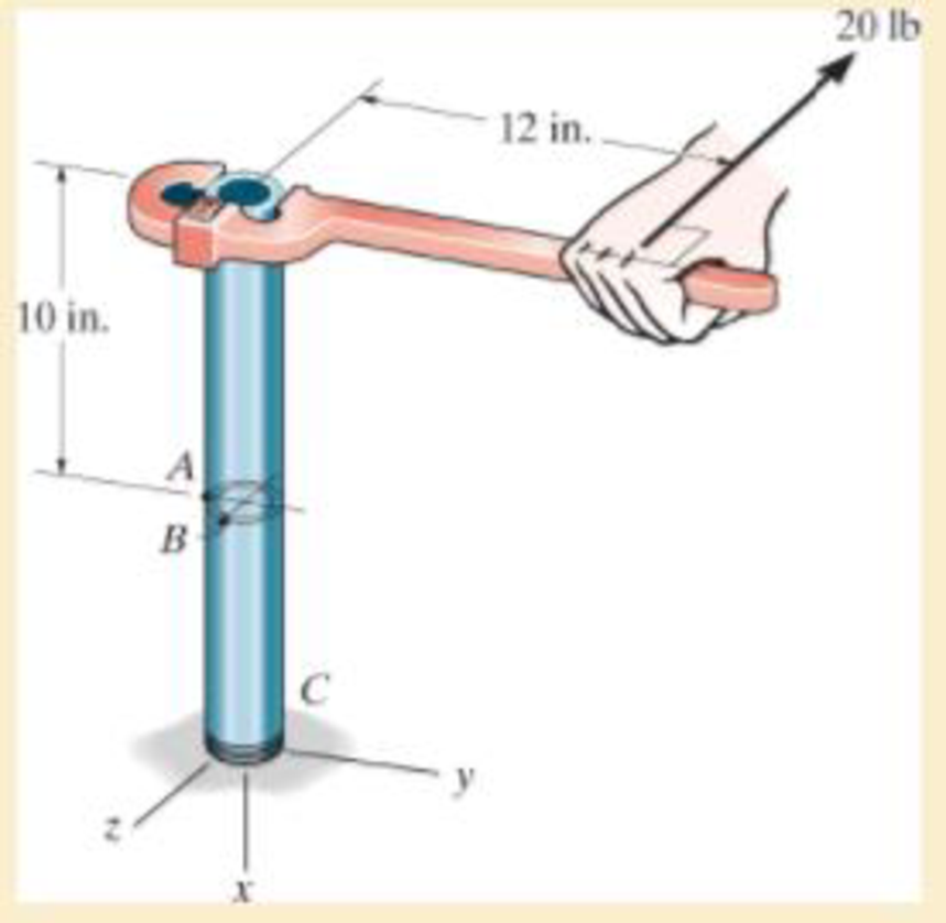
The steel pipe has an inner diameter of 2.75 in. and an outer diameter of 3 in. If it is fixed at C and subjected to the horizontal 20-lb force acting on the handle of the pipe wrench, determine the principal stresses in the pipe at point B, which is located on the surface of the pipe.
Expert Solution & Answer
Want to see the full answer?
Check out a sample textbook solution
Students have asked these similar questions
University of Babylon
Collage of Engineering/
Al-Musayab
Department of Automobiles
Mid Examination/ Stage: 3rd
Subject: Theory of Vehicles
Date: 14 \ 4 \2025
Time: 1.5 Hours
2025-2024
Q1: The arms of a Porter governor are 250 mm long. The upper arms are pivoted on
the axis of revolution, but the lower arms are attached to a sleeve at a distance of 50
mm from the axis of rotation. The weight on the sleeve is 600 N and the weight of
each ball is 80 N. Determine the equilibrium speed when the radius of rotation of the
balls is 150 mm. If the friction is equivalent to a load of 25 N at the sleeve, determine
the range of speed for this position.
Q2: In a loaded Proell governor shown in Figure below each ball weighs 3 kg and
the central sleeve weighs 25 kg. The arms are of 200 mm length and pivoted about
axis displaced from the central axis of rotation by 38.5 mm, y=238 mm, x=303.5
mm, CE 85 mm, MD 142.5 mm. Determine the equilibrium speed.
Fe
mg
E
M
2
Q3: In a spring loaded Hartnell type…
Q.2: (15 Marks)
=
1400
For the following system, determine the first natural frequency using Dunkerley's equation,
Given that the disk has moment of inertia J = 2 kg.m², the shaft has G = 20 GPa, p
kg/m³, polar moment of cross-sectional area of the shaft Ip = 8×10⁸ m².
500 mm
220 mm
k=200 N/m
FOF
m=1 kg
14.14
56.56. W
сл
Chapter 9 Solutions
Mechanics of Materials
Ch. 9.3 - In each case, the state of stress x, y, xy...Ch. 9.3 - Given the state of stress shown on the element,...Ch. 9.3 - Determine the normal stress and shear stress...Ch. 9.3 - Determine the equivalent state of stress on an...Ch. 9.3 - Also, find the corresponding orientation of the...Ch. 9.3 - Determine the equivalent state of stress on an...Ch. 9.3 - Determine the maximum principal stress at point B.Ch. 9.3 - Determine the principal stress at point C.Ch. 9.3 - Prove that the sum of the normal stresses x + y =...Ch. 9.3 - 9-2. The state of stress at a point in a member is...
Ch. 9.3 - Determine the stress components acting on the...Ch. 9.3 - Determine the normal stress and shear stress...Ch. 9.3 - Determine the normal stress and shear stress...Ch. 9.3 - 9-6. Determine the normal stress and shear stress...Ch. 9.3 - 9-7. Determine the normal stress and shear stress...Ch. 9.3 - *9-8. Determine the equivalent state of stress on...Ch. 9.3 - 9-9. Determine the equivalent state of stress on...Ch. 9.3 - Determine the equivalent state of stress on an...Ch. 9.3 - Determine the equivalent slate of stress on an...Ch. 9.3 - *9-12. Determine the equivalent state of stress on...Ch. 9.3 - 9-13. Determine the equivalent state of stress on...Ch. 9.3 - 9-14. The state of stress at a point is shown on...Ch. 9.3 - The state of stress at a point is shown on the...Ch. 9.3 - Determine the equivalent state of stress on an...Ch. 9.3 - Determine the equivalent state of stress on an...Ch. 9.3 - A point on a thin plate is subjected to the two...Ch. 9.3 - Determine the equivalent state of stress on an...Ch. 9.3 - *9-20. Planes AB and BC at a point are subjected...Ch. 9.3 - The stress acting on two planes at a point is...Ch. 9.3 - The grains of wood in the board make an angle of...Ch. 9.3 - The wood beam is subjected to a load of 12 kN. If...Ch. 9.3 - *9-24. The wood beam is subjected to a load of 12...Ch. 9.3 - 9-25. The wooden block will fail if the shear...Ch. 9.3 - 9-26. The bracket is subjected to the force of 3...Ch. 9.3 - 9-27. The bracket is subjected to the force of 3...Ch. 9.3 - 9-28. The 25-mm thick rectangular bar is subjected...Ch. 9.3 - 9-29. The 3-in. diameter shaft is supported by a...Ch. 9.3 - 9-30. The state of stress at a point in a member...Ch. 9.3 - 9-31. Determine the principal stress at point A on...Ch. 9.3 - 9-32. Determine the maximum in-plane shear stress...Ch. 9.3 - 9-33. The clamp bears down on the smooth surface...Ch. 9.3 - 9-34. Determine the principal stress and the...Ch. 9.3 - 9-35. The square steel plate has a thickness of 10...Ch. 9.3 - *9-36. The square steel plate has a thickness of...Ch. 9.3 - The shaft has a diameter d and is subjected to the...Ch. 9.3 - Prob. 9.38PCh. 9.3 - Prob. 9.39PCh. 9.3 - The wide-flange beam is subjected to the 50-kN...Ch. 9.3 - Solve Pro b. 9-40 for point B located on the web...Ch. 9.3 - Prob. 9.42PCh. 9.3 - Prob. 9.43PCh. 9.4 - Use Mohrs circle to determine the normal stress...Ch. 9.4 - Also, find the corresponding orientation of the...Ch. 9.4 - Draw Mohrs circle and determine the principal...Ch. 9.4 - Determine the principal stresses at a point on the...Ch. 9.4 - Determine the principal stresses at point A on the...Ch. 9.4 - Point A is just below the flange.Ch. 9.4 - Solve Prob.93 using Mohrs circle. 93. Determine...Ch. 9.4 - 9-45. Solve Prob. 9-6 using Mohr’s circle.
9-6....Ch. 9.4 - 9-46. Solve Prob. 9-14 using Mohr’s circle.
9-14....Ch. 9.4 - Solve Prob.911 using Mohrs circle. 911. Determine...Ch. 9.4 - *9-48. Solve Prob. 9-12 using Mohr’s...Ch. 9.4 - Solve Prob.916 using Mohrs circle. 916. Determine...Ch. 9.4 - Mohrs circle for the state of stress is shown in...Ch. 9.4 - Prob. 9.51PCh. 9.4 - Prob. 9.52PCh. 9.4 - 9-53. Determine the equivalent state of stress if...Ch. 9.4 - Prob. 9.54PCh. 9.4 - Prob. 9.55PCh. 9.4 - Prob. 9.56PCh. 9.4 - Determine (a) the principal stresses and (b) the...Ch. 9.4 - 9-58. Determine the equivalent state of stress if...Ch. 9.4 - Prob. 9.59PCh. 9.4 - Prob. 9.60PCh. 9.4 - 9-61. Draw Mohr’s circle that describes each of...Ch. 9.4 - The grains of wood in the board make an angle of...Ch. 9.4 - The post is fixed supported at its base and a...Ch. 9.4 - Determine the principal stresses, the maximum...Ch. 9.4 - The thin-walled pipe has an inner diameter of 0.5...Ch. 9.4 - 9-66. Determine the principal stress and maximum...Ch. 9.4 - Prob. 9.67PCh. 9.4 - The rotor shaft of the helicopter is subjected to...Ch. 9.4 - The pedal crank for a bicycle has the cross...Ch. 9.4 - A spherical pressure vessel has an inner radius of...Ch. 9.4 - The cylindrical pressure vessel has an inner...Ch. 9.4 - Determine the normal and shear stresses at point D...Ch. 9.4 - Determine the principal stress at point D, Which...Ch. 9.4 - If the box wrench is subjected to the 50 lb force,...Ch. 9.4 - If the box wrench is subjected to the 50-lb force,...Ch. 9.4 - Prob. 9.76PCh. 9.5 - Draw the three Mohrs circles that describe each of...Ch. 9.5 - Draw the three Mohrs circles that describe the...Ch. 9.5 - 9-79. The stress at a point is shown on the...Ch. 9.5 - Determine the principal stresses and the absolute...Ch. 9.5 - 9-81. The stress at a point is shown on the...Ch. 9.5 - Determine the principal stresses and the absolute...Ch. 9.5 - Determine the principal stresses and the absolute...Ch. 9.5 - Prob. 9.85PCh. 9.5 - Prob. 9.86PCh. 9.5 - 9-87. Determine the principal stresses and...Ch. 9.5 - *9.88. Determine the principal stresses and...Ch. 9 - Prob. 9.89RPCh. 9 - Prob. 9.90RPCh. 9 - Prob. 9.91RPCh. 9 - The steel pipe has an inner diameter of 2.75 in....Ch. 9 - Determine the equivalent state of stress If an...Ch. 9 - The crane is used to support the 350-lb load....Ch. 9 - Determine the equivalent state of stress on an...Ch. 9 - The propeller shaft of the tugboat is subjected to...Ch. 9 - Determine the principal stresses in the box beam...Ch. 9 - Determine (a) the principal stresses and (b) the...Ch. 9 - Determine the stress components acting on the...
Additional Engineering Textbook Solutions
Find more solutions based on key concepts
The ____________ is always transparent.
Web Development and Design Foundations with HTML5 (8th Edition)
How are relationships between tables expressed in a relational database?
Modern Database Management
17–1C A high-speed aircraft is cruising in still air. How does the temperature of air at the nose of the aircra...
Thermodynamics: An Engineering Approach
This optional Google account security feature sends you a message with a code that you must enter, in addition ...
SURVEY OF OPERATING SYSTEMS
CONCEPT QUESTIONS
15.CQ3 The ball rolls without slipping on the fixed surface as shown. What is the direction ...
Vector Mechanics for Engineers: Statics and Dynamics
How does a computers main memory differ from its auxiliary memory?
Java: An Introduction to Problem Solving and Programming (8th Edition)
Knowledge Booster


Learn more about
Need a deep-dive on the concept behind this application? Look no further. Learn more about this topic, mechanical-engineering and related others by exploring similar questions and additional content below.Similar questions
- Q1: In Figure below, pinion A having 15 teeth is fixed to motor shaft. Za-20, Z-15, where B and C are a compound gear wheel. Wheel E is keyed to the machine shaft. Arm F rotates about the same shaft on which A is fixed and carries the compound wheel B, C. If the motor runs at 1200 rpm counter-clockwise, find (a) the speed of the machine shaft and (b) ratio of the reduction gear. C B D Q1: A compound epicyclic gear is shown diagrammatically in Figure below. The gears A, D and E are free to rotate on the axis P. The compound gear B and C rotate together on the axis Q at the end of arm F. All the gears have equal pitch. The number of external teeth on the gears A, B and C are 18, 45 and 21 respectively. The gears D and E are annular gears. The gear A rotates at 100 r.p.m. in the anticlockwise direction and the gear D rotates at 450 r.p.m. clockwise. Find the speed and direction of the arm and the gear E. D E A P F LL B Carrow_forwardCalculate the force in cable AB and the angle θ for the support system shown. Round your final answers to two decimal places.arrow_forward1.53 In the steel structure shown, a 6-mm-diameter pin is used at C and 10-mm-diameter pins are used at B and D. The ultimate shearing stress is 150 MPa at all connections, and the ultimate normal stress is 400 MPa in link BD. Knowing that a factor of safety of 3.0 is desired, determine the largest load P that can be applied at A. Note that link BD is not reinforced around the pin holes. Front view D D 6 mm 18 mm B A B Side view 160 mm 120 mm A B Top viewarrow_forward
- CORRECT AND DETAILED HANDWRITTEN SOLUTION WITH FBD ONLY. I WILL UPVOTE THANK YOU. CORRECT ANSWER IS ALREADY PROVIDED. 16: Determine (a) the maximum bending stress, (b)the maximum shearing stress, (c) compressive bending stress atthe roller support, and (d) the shearing stress 1 in below the topsurface of the beam at the location 1 ft to the right of the rollersupport in the simply supported beam shown in Fig. 8-70.ANS: (a) 21,945.313 lb/in2; (b) 1656.25 lb/in2; (c) 10,000 lb/in2; (d) 190.972 lb/in2arrow_forwardCORRECT AND DETAILED HANDWRITTEN SOLUTION WITH FBD ONLY. I WILL UPVOTE THANK YOU. CORRECT ANSWER IS ALREADY PROVIDED. 20: A 2022 Porsche 911 (992) GT3 is crossing a 20 ft bridge. The specification of the car is shown below.Determine the maximum shear (in lb) and moment (in lb-ft) on the bridge. ANS: Vmax = 2,680.850 lb ; Mmax = 11,233.13 lb-ftarrow_forwardCORRECT AND DETAILED HANDWRITTEN SOLUTION WITH FBD ONLY. I WILL UPVOTE THANK YOU. CORRECT ANSWER IS ALREADY PROVIDED. Answers: P1 = 208.625 KN/M P2 = 281.310 KN/M P = 15.491 KN/M FB = 463.402 MPA FV = 55.034 MPAarrow_forward
- CORRECT AND DETAILED HANDWRITTEN SOLUTION WITH FBD ONLY. I WILL UPVOTE THANK YOU. CORRECT ANSWER IS ALREADY PROVIDED. 18: Determine the maximum shear and moment that would be experienced by a 10 m beam if a three-wheelmoving load of 10 kN, 30 kN, and 5 kN respectively will pass it by. The distance between the 1st and 2nd load is 1 m and the distance between the 2nd and 3rd load is 3 m.ANS: Vmax = 40 kN ; Mmax = 100.014 kN-marrow_forwardCORRECT AND DETAILED HANDWRITTEN SOLUTION WITH FBD ONLY. I WILL UPVOTE THANK YOU. CORRECT ANSWER IS ALREADY PROVIDED. 5: A 12-m simply supported bridge is constructed with 100-mm concrete slab deck supported by precastconcrete stringers spaced 800 mm on center. Analyze the stringers when subjected to a moving load consisting of 3 evenly spaced axle loads at 3 m and equivalent to 20 kN, 30 kN and 40 kN respectively. The self-weight of the stringers is 8.5 kN/m and the concrete deck has a unit weight of 24 kN/m3 . Neglect all other superimposed loads. Calculate: (a) the maximum shear force in the stringers; (b) the maximum bending moment in the stringers. Answer: Vmax = 135.020 KN, Mmax = 477.388 KN-Marrow_forwardCORRECT AND DETAILED HANDWRITTEN SOLUTION WITH FBD ONLY. I WILL UPVOTE THANK YOU. CORRECT ANSWER IS ALREADY PROVIDED. 19: A 22-wheeler truck is crossing over 25 m bridge. The dimensions between the axles of the truck are shownin the figure below. Axles 1 to 3 carry a 90 kN load each, axles 4 and 5 carry a 65 kN load each, and the axle directly below the cab of the truck has a load of 100 kN. Determine the maximum shear and moment on the bridge.ANS: Vmax = 374.92 kN ; Mmax = 1,702.229 kN-marrow_forward
- CORRECT AND DETAILED HANDWRITTEN SOLUTION WITH FBD ONLY. I WILL UPVOTE THANK YOU. CORRECT ANSWER IS ALREADY PROVIDED. 1. A H = 6 m cantilever retaining wall is subjected to a soil pressurelinearly varying from zero at the top to 90 kPa at the bottom. As an additionalsupport, it is anchored at depth y = 2 m. with maximum tension equal to 25kN. Assume that the stem provides fully retrained support. Draw the shearand moment diagram of the wall to calculate the following: (a) Maximumpositive bending moment per linear meter; (b) maximum negative bendingmoment per linear meter; (c) maximum shear force per linear meter. answer: +MMax = 440 kn-m, -Mmax = 0kn-M, Vmax = 245 KNarrow_forwardCORRECT AND DETAILED HANDWRITTEN SOLUTION WITH FBD ONLY. I WILL UPVOTE THANK YOU. CORRECT ANSWER IS ALREADY PROVIDED. 17: A simply supported beam with the section shown below has an allowableflexural shearing stress of 43 MPa. (a) Determine the maximum allowable shearing force onthe section. And (b) what is the minimum thickness of plate that should be welded at theflanges if the section is to withstand a total shearing force of 200 kN. The additional plate willhave its base dimension equal to the flange dimension.ANS: V = 179.333 kN ; t = 23.181 mmarrow_forwardCORRECT AND DETAILED HANDWRITTEN SOLUTION WITH FBD ONLY. I WILL UPVOTE THANK YOU. CORRECT ANSWER IS ALREADY PROVIDED. Answer: A = 0.207 L(M)arrow_forward
arrow_back_ios
SEE MORE QUESTIONS
arrow_forward_ios
Recommended textbooks for you
 Elements Of ElectromagneticsMechanical EngineeringISBN:9780190698614Author:Sadiku, Matthew N. O.Publisher:Oxford University Press
 Mechanics of Materials (10th Edition)Mechanical EngineeringISBN:9780134319650Author:Russell C. HibbelerPublisher:PEARSON
 Thermodynamics: An Engineering ApproachMechanical EngineeringISBN:9781259822674Author:Yunus A. Cengel Dr., Michael A. BolesPublisher:McGraw-Hill Education
 Control Systems EngineeringMechanical EngineeringISBN:9781118170519Author:Norman S. NisePublisher:WILEY
 Mechanics of Materials (MindTap Course List)Mechanical EngineeringISBN:9781337093347Author:Barry J. Goodno, James M. GerePublisher:Cengage Learning
 Engineering Mechanics: StaticsMechanical EngineeringISBN:9781118807330Author:James L. Meriam, L. G. Kraige, J. N. BoltonPublisher:WILEY
Elements Of Electromagnetics
Mechanical Engineering
ISBN:9780190698614
Author:Sadiku, Matthew N. O.
Publisher:Oxford University Press
Mechanics of Materials (10th Edition)
Mechanical Engineering
ISBN:9780134319650
Author:Russell C. Hibbeler
Publisher:PEARSON
Thermodynamics: An Engineering Approach
Mechanical Engineering
ISBN:9781259822674
Author:Yunus A. Cengel Dr., Michael A. Boles
Publisher:McGraw-Hill Education
Control Systems Engineering
Mechanical Engineering
ISBN:9781118170519
Author:Norman S. Nise
Publisher:WILEY
Mechanics of Materials (MindTap Course List)
Mechanical Engineering
ISBN:9781337093347
Author:Barry J. Goodno, James M. Gere
Publisher:Cengage Learning
Engineering Mechanics: Statics
Mechanical Engineering
ISBN:9781118807330
Author:James L. Meriam, L. G. Kraige, J. N. Bolton
Publisher:WILEY
Pressure Vessels Introduction; Author: Engineering and Design Solutions;https://www.youtube.com/watch?v=Z1J97IpFc2k;License: Standard youtube license