
Concept explainers
(a)
To select the
Answer to Problem 9.8.7P
The beam
Explanation of Solution
Given:
Thickness of slab, t = 5.0 inches, spacing = 7.0 ft, span length, L = 30 feet, yield stress = 50 Ksi
Construction load = 20 psf, and live load = 800 psf.
The value of
Calculation:
Using LRFD method, we select a suitable shape that will satisfy the given conditions:
Calculate the loads on the beam as follows:
After curing we have,
Where,
between two adjacent beams.
The dead load on the beam after the concrete has cured is:
Calculate the live load on the beam using the following equation:
Where,
Calculate the factored uniformly distributed load after curing has completed by following formula:
Where,
Substitute the values, we get
Calculate the bending moment on the beam;
Where,
Try for
| DesignationImperial (in x lb/ft) | Depthh (in) | Widthw (in) | Web Thicknesstw (in) | Flange Thicknesstf (in) | Sectional Area (in2) | Weight (lbf/ft) | Static Parameters | |||
| Moment of Inertia | Elastic Section Modulus | |||||||||
| Ix (in4) | Iy (in4) | Sx (in3) | Sy (in3) | |||||||
| W 24 x 76 | 23.9 | 9 | 0.440 | 0.680 | 22.4 | 76 | 2100 | 82.5 | 176 | 18.4 |
Calculate the distance of the plastic neutral axis from the top of the slab as follows:
Where, b is the width of the concrete slab, t is the thickness of the concrete beam,
The effective flange width is as follows;
Substitute the values, we have
Compute the value of Y as shown below:
From the manual the value of nominal flexural strength of the beam
Comparing the values of
Thus, the beam is satisfactory excluding its self-weight.
Now for including the weight of the beam, we have
Calculate the factored uniformly distributed load after curing has completed by following formula:
Where,
Substitute the values, we get
Calculate the maximum bending moment on the beam;
Where,
Check the flexural strength of the beam including its weight.
Thus, the beam is satisfactory including its self-weight.
Check for the shear:
Checking the value of nominal value of shear strength of
Where,
The maximum shear force is as following for the above conditions:
Substitute the values, we have
Now comparing the two we have
Therefore, the beam is safe in shear and we can use
Calculate the factored uniformly distributed load before curing has completed by following formula:
Where,
Where,
between two adjacent beams.
The dead load on the beam before the concrete has cured is:
Calculate the live load on the beam using the following equation:
Where,
Substitute the values, we get
Calculate the maximum bending moment on the beam;
Where,
Check for the value of nominal flexural strength, the flexural strength of the beam before curing is
Comparing the values of
Therefore, the beam is satisfactory before the curing has completed.
Now calculating the maximum allowable live load deflection from the given beam using the formula as:
Substitute the values, we have
We have the value of lower bound moment of inertia for the given condition as follows:
Calculating the total load on the beam using the following :
Where,
Now by comparing the values, we have
Conclusion:
Hence, the beam
(b)
Use ASD method to select the
Answer to Problem 9.8.7P
The beam
Explanation of Solution
Calculation:
Now, we will use allowable stress design
Calculate the loads on the beam as follows:
After curing we have,
Where,
between two adjacent beams.
The dead load on the beam after the concrete has cured is:
Calculate the live load on the beam using the following equation:
Where,
Calculate the allowable uniformly distributed load after curing has completed by following formula:
Where,
Substitute the values, we get
Calculate the bending moment on the beam;
Where,
Compute the value of Y, which is the distance from the top of steel shape to compressive force
in concrete and is shown below:
Try for
Calculate the distance of the plastic neutral axis from the top of the slab as follows:
Where, b is the width of the concrete slab, t is the thickness of the concrete beam,
The effective flange width is as follows;
Substitute the values, we have
Compute the value of Y as shown below:
From the table 3-19 of the ASIC manual:
Trying for
Check whether the section is safe in flexure if the self -weight is excluded
Where,
Now comparing the values of
Substitute the values, we have
Therefore, the section is safe in flexure if the self -weight is excluded.
Let’s check for the beam weight :
Calculation of the maximum bending moment as follows:
Substitute the values, we get
Now check for the flexural strength including the beam weight:
Comparing the values of maximum bending moment and the nominal flexural strength as follows:
Therefore, the section is safe in flexure including the self-weight of the beam.
Check for the shear:
Checking the value of nominal value of shear strength of
Where,
The maximum shear force is as following for the above conditions:
Substitute the values, we have
Now comparing the two we have
Therefore, the beam is safe in shear and we can use
Calculate the loads on the beam as follows:
Before curing we have,
Where,
between two adjacent beams.
The dead load on the beam before the concrete has cured is:
Calculate the live load on the beam using the following equation:
Where,
Substitute the values, we get
Calculate the maximum bending moment on the beam;
Where,
Checking the value of nominal flexural strength of W- section from the ZX table of the ASIC manual:
Check whether the section is safe in flexure if the self -weight is excluded
Where,
Now comparing the values of
Substitute the values, we have
Therefore, the section is safe in before the curing of concrete.
Now calculating the maximum allowable live load deflection from the given beam using the formula as:
Substitute the values, we have
We have the value of lower bound moment of inertia for the given condition as follows:
Calculating the total load on the beam using the following :
Where,
Now by comparing the values, we have
Conclusion:
Hence, the beam
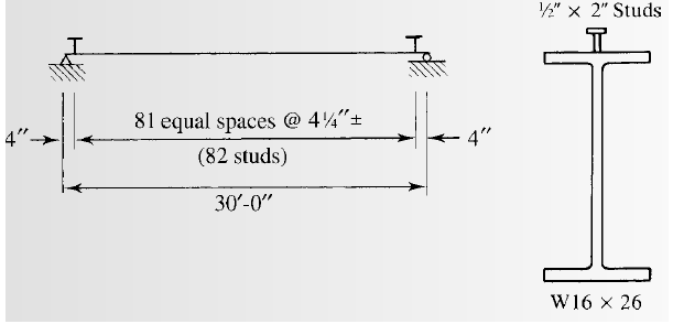
(c)
Selecting the stud anchors.
Answer to Problem 9.8.7P
We will use
Explanation of Solution
Calculation:
From AISC specifications, compute the maximum stud diameter using the equation:
Where,
Substitute the values, we get
Try for the studs of size
From table 3-21 for lightweight concrete take one stud at each of the beam position.
The number of studs for half beam can be found as follows:
Substitute the values, we have
Compute the number of studs as follows:
Substitute the value of
Calculate the spacing of the studs as follows:
Compute the minimum longitudinal spacing for studs using the equation
Where,
Substitute the values
Compute the minimum transverse spacing for studs using the equation
Where,
Substitute the values
Compute the maximum longitudinal spacing for studs using the equation
Where,
Substitute the values
But the upper limit of the spacing is 36 inches.
Calculate the require spacing for one stud at each of the section:
Substitute the values, we have
Conclusion:
Therefore, we will use
Want to see more full solutions like this?
Chapter 9 Solutions
Steel Design (Activate Learning with these NEW titles from Engineering!)


- Given a portion of a pipe network below. Determine the true discharge in each pipe using the Hardy-Cross method. Use the Darcy-Weisbach formula with f = 0.02 for all pipes. Pipe AB Length (m) Diameter (cm) 600 25 BC 400 25 CD 900 30 DA AC 1000 20 1500 20 Q₁₁ = 0.20 m³/s B Qc = 0.30 m³/s Loop I QA 0.10 m³/s A. C Loop II Q₁ = 0.20 m³/sarrow_forwardThe figures below shows the framing plan and section of a reinforced concrete floor system. Floor beams are shown as dotted lines. The weight of the ceiling and floor finishing is 6 psf, that of the mechanical and electrical systems is 7 psf, and the weight of the partitions is 180 psf. The floor live load is 105 psf. The 7 in. thick slab exterior bay (S-1) is reinforced with #5 rebars @ 10 in. o.c. as the main positive reinforcement at the mid span, and #4 @ 109 in. for the shrinkage and temperature reinforcement. The panel is simply supported on the exterior edge and monolithic with the beam at the interior edge. Check the adequacy of the slab. Use the ACI moment coefficients. fc’ = 6,000 psi and fy = 60,000 psi. The slab is in an interior location. Hint: • Estimate total dead load. Find factored maximum positive bending moment in the end span. • Find design positive moment capacity. • Compare and determine adequacy, including safety and economy.arrow_forwardQuestion 6 Two reservoirs have a 6 m difference in water levels and are connected by a pipe 60 cm in diameter and 3000 m long. Then, the pipe branches into two pipes, each 30 cm in diameter and 1500 m long. The friction coefficient is 0.01. Neglecting minor losses, determine the flow rates in the pipe system. Q Q3 ha h₁ = 6 marrow_forward
- Design a simply supported one-way pavement slab for a factored applied moment, Mu = 10 ft- kip. Use f c’ = 5,000 psi and f y = 60,000 psi. The slab is in permanent contact with soil. Hint: • Estimate a minimum slab thickness for deflection control. • Solve for the slab steel based on cover for soil contact.arrow_forward20. In a deterministic queue, suppose vehicle arrive at a rate of 100 vph for the first hour and 60 vph for the second hour. The server can discharge 80 vehicles per hour. What is the standing queue at the end of two hours:arrow_forwardThe difference in water surface levels in two tanks, which are connected by three pipes in series of lengths 400 m, 200 m, and 300 m and of diameters 400 mm, 300 mm, and 200 mm, respectively, is 16m. Estimate the rate of flow of water if the coefficient of friction for these pipes is same and equal to 0.005, considering: (i) minor losses also (ii) neglecting minor losses.arrow_forward
- The difference in water surface levels in two tanks, which are connected by three pipes in series of lengths 300 m, 170 m, and 210 m, having diameters 300 mm, 200 mm, and 400 mm, respectively, is 12 m. Determine the rate of flow of water if coefficients of friction are 0.005, 0.0052, and 0.0048, respectively. Determine the discharge and velocity in each pipe, considering the minor losses and neglecting minor losses.arrow_forwardDetermine the heel and toe stresses and the factor of safeties for sliding and overturning for the gravity dam section shown in the figure below for the following loading conditions: - Horizontal earthquake (Kh) = 0.1 - Normal uplift pressure with gallery drain working - Silt deposit up to 30 m height - No wave pressure and no ice pressure -Unit weight of concrete = 2.4 Ton/m³ and unit weight of silty water = 1.4 Ton/m³ - Submerged weight of silt = 0.9 Ton/m³ - Coefficient of friction = 0.65 and angle of repose = 25° Solve this question with the presence of gallery and without gallery., discuss the issue in both cases.... Draw and Solve in table 4m 8m 6m 8m 7m 120marrow_forwardLand Use Hydrologic Area (acres) Soil Group A 25 Forestland-orchards B 30 B 45 Forest Oak-Aspen C 60 A 80 Open Spaces B 65 A 120 Residential (1/2-acre lots) B 155 Storm Hyetograph Time Rainfall Interval Intensity (hours) (in/hr) 0-1 1.2 1-2 1.3 2-3 1.9 3-4 1.5 4-5 1.3 5-6 1 6-7 0.8 1 Hour-Unit Hydrograph Time UH [hr] [cfs/in] 0 0 1 60 2 120 3 140 4 80 5 40 6 10 7 0arrow_forward
- Secondary Treatment Based on a plant flow rate of 40 mgd, design an activated sludge, secondary treatment system with recycle which maintains a MLVSS = 2,000 mg/L in the aeration reactor and has an average Solids Retention Time (SRT) = 4 days. The biota kinetic constants are: Kinetic Coefficients for the Activated-sludge Process for the Removal of Organic Matter from Domestic Wastewater - Endogenous Decay Coefficient – k(d) Half-velocity constant – K(s) 0.1 15 Max. Specific Substrate Utilization Rate – k Biomass Yield - Y 6 0.45 gVSS/gVSS-day mg/L bsCOD g bsCOD/gVSS-day gVSS/g bsCOD used The laboratory has provided the information below for your influent from your primary clarifier. Unit mg/L Item Influent nbVSS - Xo Quantity 30 Fraction of the biomass which remains as cell debris (fd) Temperature 0.18 20 °C Quantity of Oxygen in air 0.017 Lb O₂/ft³ air Influent microorganism & substrate concentration as (So) Influent Inert Inorganics (TSS. – VSS.) 215 10 Mg/L bsCOD mg/L Aeration Basin…arrow_forwardPlease explain step by step and show formulaarrow_forwardThree pipes of length 800 m, 500 m, and 400 m and diameters of 500 mm, 400 mm, and 300 mm, respectively, are connected in a series. These pipes are to be replaced by a single pipe of length 1700 m. Find the diameter of the single pipe.arrow_forward
 Steel Design (Activate Learning with these NEW ti...Civil EngineeringISBN:9781337094740Author:Segui, William T.Publisher:Cengage Learning
 Materials Science And Engineering PropertiesCivil EngineeringISBN:9781111988609Author:Charles GilmorePublisher:Cengage Learning
 Traffic and Highway EngineeringCivil EngineeringISBN:9781305156241Author:Garber, Nicholas J.Publisher:Cengage Learning
 Architectural Drafting and Design (MindTap Course...Civil EngineeringISBN:9781285165738Author:Alan Jefferis, David A. Madsen, David P. MadsenPublisher:Cengage Learning
 Construction Materials, Methods and Techniques (M...Civil EngineeringISBN:9781305086272Author:William P. Spence, Eva KultermannPublisher:Cengage Learning
 Fundamentals Of Construction EstimatingCivil EngineeringISBN:9781337399395Author:Pratt, David J.Publisher:Cengage,