
Concept explainers
(a)
Use LFRD method to select the
Answer to Problem 9.5.1P
Explanation of Solution
Given:
Thickness of slab, t = 4.5 inches, spacing = 6.5 ft, span length, L = 36 feet, yield stress = 50 Ksi
Construction load = 20 psf, and live load = 175 psf.
The value of
Concept Used:
Calculation:
Using LRFD method, we have
To select the suitable W 16 shape as follows:
Calculate the loads on the beam as follows:
After curing we have,
Where,
between two adjacent beams.
The dead load on the beam after the concrete has cured is:
Where,
Neglecting the beam weight and check for it later.
Calculate the live load on the beam using the following equation:
Where,
Calculate the factored uniformly distributed load after curing has completed by the following formula:
Where,
Substitute the values, we get
Calculate the bending moment on the beam;
Where,
Let’s try a 16-inch deep beam.
Select a shape with the limiting self-weight given by the following formula:
Where, t is the thickness of the concrete slab, d is the depth of the steel beam, a is the distance of the neutral axis from the top,
Estimating weight per unit foot of the steel beam as:
Let’s try for W 16 X 31 and note the properties and dimensions from the Manual.
Calculate the strength of the section as following below:
Where, the compressive force is C, the compressive force of concrete is
Calculate the compressive force in steel as follows:
Where, the area of steel section is
Get the value of
Calculate the compressive force in concrete as following:
Where, b is the width of the concrete slab, t is the thickness of the concrete beam and
The effective flange width is as follows:
Substitute the values in the above equation, we get
Therefore, the compressive force is as follows:
Therefore, the plastic neutral axis lies in the slab.
Calculate the tensile force (T) and compressive force (C) and the position of plastic neutral axis from the top of concrete slab by following formula:
Compute the flexural strength as:
Where,
neutral axis.
Compute the value of Y as following below:
Substitute the values, we get
Calculate the design strength of the section as follows:
Where,
Substitute the values, we get
The flexural strength of the beam after curing is given as:
Where,
Comparing the values of
Thus, the beam is satisfactory in bending after the curing of concrete is complete.
Check for beam weight.
Where,
Substitute the values, we get
Calculate the maximum bending moment on the beam;
Where,
Check the flexural strength of the beam.
Compare the maximum bending moment and the nominal flexural strength
Comparing the values of
Thus, the section is safe in flexure including its self-weight.
Check for the shear:
Checking the value of nominal value of shear strength of
Where,
The maximum shear force is as following for the above conditions:
Substitute the values, we have
Now comparing the two we have
Therefore, the beam is safe in shear and we can use
Calculate the factored uniformly distributed load after curing has completed by following formula:
Load before curing:
Calculate the self-weight of the slab to be allowed by a single beam as
Where,
The dead load on the beam before the concrete has cured
Where, w is the self-weight of the beam
Substitute the values, we have
Now, calculate the live load on the beam as follows
Where the construction load on the slab is
The uniformly distributed factored load can be found as
Where,
Substitute the values in the above equation, we have
Calculate the maximum bending moment on the beam.
Where,
Check the value of the nominal flexural strength of W- sections from the Manual:
Flexural strength of the beam before curing is given as follows:
Where,
Comparing the values of
Thus, the beam is satisfactory before the curing of concrete is complete.
Therefore, W 16 X 31 is satisfactory to use.
Conclusion:
Therefore,
(b)
Use ASD method to select the
Answer to Problem 9.5.1P
Explanation of Solution
Calculation:
Applying Allowable stress design:
Select appropriate W 16 shape
Calculate the loads on the beam as follows:
Before curing
Calculate the self-weight of the slab to be allowed by a single beam as follows:
Where,
between two adjacent beams.
The dead load on the beam after the concrete has cured is:
Where,
Neglecting the beam weight and check for it later.
Calculate the live load on the beam using the following equation:
Where,
Calculate the allowable uniformly distributed load as follows:
Substitute the values as follows
Calculate the bending moment on the beam;
Where,
Let’s try a 16-inch deep beam.
Select a shape with the limiting self-weight given by the following formula:
Where, t is the thickness of the concrete slab, d is the depth of the steel beam, a is the distance of the neutral axis from the top,
Estimating weight per unit foot of the steel beam as:
Let’s try for W 16 X 31 and note the properties and dimensions from the Manual.
Calculate the strength of the section as following below:
Where, the compressive force is C, the compressive force of concrete is
Calculate the compressive force in steel as follows:
Where, the area of steel section is
Get the value of
Calculate the compressive force in concrete as following:
Where, b is the width of the concrete slab, t is the thickness of the concrete beam and
The effective flange width is as follows;
Substitute the values in the above equation, we get
Therefore, the compressive force is as follows:
Therefore, the plastic neutral axis lies in the slab.
Calculate the tensile force (T) and compressive force (C) and the position of plastic neutral axis from the top of concrete slab by following formula:
Compute the flexural strength as:
Where,
neutral axis.
Compute the value of Y as following below:
Substitute the values, we get
Calculate the design strength of the section as follows:
Where,
Substitute the values, we get
Check the nominal value of the flexural strength of W- sections from the manual.
Where,
Comparing the values, we get
Thus, the beam is satisfactory after curing of concrete has completed.
Check for beam weight
Calculating the max bending mo0ment by busing the following formula:
Substitute the values as follows:
Now, checking the flexural strength with the beam taken into consideration:
Compare the maximum bending moment and the nominal flexural strength
Comparing the values of
Thus, the section is safe in flexure including its self-weight.
Check for the shear:
Checking the value of nominal value of shear strength of
Where,
The maximum shear force is as following for the above conditions:
Substitute the values, we have
Now comparing the two we have
Therefore, the beam is safe in shear.
Loading before curing:
Calculate the self-weight of the slab to be allowed by a single beam as follows:
Where,
between two adjacent beams.
The dead load on the beam before the concrete has cured
Where, w is the self-weight of the beam
Substitute the values, we have
Now, calculate the live load on the beam as follows
Where the construction load on the slab is
The uniformly distributed factored load can be found as
Where,
Substitute the values in the above equation, we have
Calculate the maximum bending moment on the beam;
Where,
Check the value of the nominal flexural strength of W- sections from the Manual:
Flexural strength of the beam before curing is given as follows:
Where,
Comparing the values of
Thus, the beam is satisfactory before the curing of concrete is complete.
Conclusion:
Therefore,
(c)
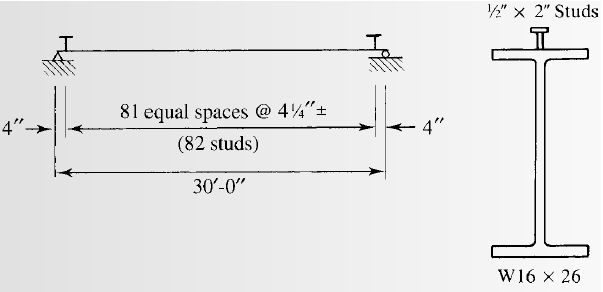
Selecting the stud anchors for the given section.
Answer to Problem 9.5.1P
we will use
Explanation of Solution
Calculation:
We have to check whether the studs satisfy the ASIC specifications.
From AISC specifications the maximum stud diameter will be equal to
Where,
Substitute the values in the equation, we get
Try for,
The area of stud using the following equation as follows:
Where, the diameter of the stud is d.
Substitute
We have the modulus of elasticity of concrete as follows:
Where, the modulus of elasticity of concrete is
unit weight of concrete is
the 28-day compressive strength of concrete is
Substitute
Calculating the shear strength of stud with the following formula:
Substitute the values, we get
Now, the upper limit of the shear strength is as follows:
As, the calculated value is less than the upper limit given by AISC, take the shear strength as:
The number of studs required for the half beam are as follows:
Substitute the values, we have
The number of studs required are as follows:
Substitute the values, we have
Calculate the spacing of the studs as following:
The minimum longitudinal spacing for the studs will be as follows:
Where, the minimum longitudinal spacing for the studs is
Substitute the values, we have
The minimum transversal spacing for the studs will be as follows:
Where, the minimum transversal spacing for the studs is
Substitute the values, we have
The maximum longitudinal spacing for the studs will be as follows:
Where, the maximum longitudinal spacing for the studs is
Substitute the values, we have
Therefore, the upper limit of the spacing is 36 inches.
Calculating the spacing for a stud at each section by the following formula:
Where, S is the spacing required
Conclusion:
Therefore, we will use
Want to see more full solutions like this?
Chapter 9 Solutions
Steel Design (Activate Learning with these NEW titles from Engineering!)


- Calculate the BMs (bending moments) at all the joints of the beam shown in Fig.1 using the Slope deflection method. The beam is subjected to an UDL of w=65m. L=4.5m L1= 1.8m. Assume the support at C is pinned, and A and B are roller supports. E = 200GPa, I = 250x106 mm4.arrow_forwardThank you for your help if you would also provide the equations used .arrow_forwardThe sectors are divided as follows:top right = 1, top left = 2, middle = 3, bottom = 4.(a) Determine the distance yˉ to the centroid of the beam’s cross-sectional area.Solve the next questions by building a table. (Table format Answers) (b) Determine the second moment of area (moment of inertia) about the x′ axis. (c) Determine the second moment of area (moment of inertia) about the y-axis.arrow_forward
- instructions: make sure to follow the instructions and provide complete and detailed solution create/draw a beam with uniformly distributed load and concentrated load after, find the shear and moment equation and ensure to draw it's shear and moment diagram once done, write it's conclusion or observation 4:57 PMarrow_forwardSolve for forces on pin C and Darrow_forwardBorrow pit soil is being used to fill an 900,00 yd3 of depression. The properties of borrowpit and in-place fill soils obtained from laboratory test results are as follows:• Borrow pit soil: bulk density 105 pcf, moisture content = 8%, and specific gravity = 2.65• In-place fill soil: dry unit weight =120 pcf, and moisture content = 16%(a) How many yd3 of borrow soil is required?(b) What water mass is needed to achieve 16% moisture in the fill soil?(c) What is the in-place density after a long rain?arrow_forward
- solve for dt/dx=f(t,x)=x+t^2arrow_forwardCalculate the BMs (bending moments) at all the joints of the beam shown in Fig.1 using the slope deflection method, draw the resulting shear force diagran and bending moment diagram. The beam is subjected to an UDL of w=65m. L=4.5m, L1= 1.8m. Assume the support at C is pinned, and A and B are roller supports. E = 200 GPa, I = 250x106 mm4.arrow_forwardProblem 2 (A is fixed and C is a pin) Find the reactions and A and C. 10 k- 6 ft 6 ft B A 2 k/ft 15 ftarrow_forward
- 6. A lake with no outlet is fed by a river with a constant flow of 1200 ft3/s. Water evaporates from the surface at a constant rate of 13 ft3/s per square mile of surface area. The surface area varies with the depth h (in feet) as A (square miles) = 4.5 + 5.5h. What is the equilibrium depth of the lake? Below what river discharge (volume flow rate) will the lake dry up?arrow_forwardProblem 5 (A, B, C and D are fixed). Find the reactions at A and D 8 k B 15 ft A -20 ft C 10 ft Darrow_forwardProblem 4 (A, B, E, D and F are all pin connected and C is fixed) Find the reactions at A, D and F 8 m B 6m E 12 kN D F 4 marrow_forward
 Steel Design (Activate Learning with these NEW ti...Civil EngineeringISBN:9781337094740Author:Segui, William T.Publisher:Cengage Learning
 Materials Science And Engineering PropertiesCivil EngineeringISBN:9781111988609Author:Charles GilmorePublisher:Cengage Learning
 Architectural Drafting and Design (MindTap Course...Civil EngineeringISBN:9781285165738Author:Alan Jefferis, David A. Madsen, David P. MadsenPublisher:Cengage Learning
 Construction Materials, Methods and Techniques (M...Civil EngineeringISBN:9781305086272Author:William P. Spence, Eva KultermannPublisher:Cengage Learning
 Traffic and Highway EngineeringCivil EngineeringISBN:9781305156241Author:Garber, Nicholas J.Publisher:Cengage Learning
 Fundamentals Of Construction EstimatingCivil EngineeringISBN:9781337399395Author:Pratt, David J.Publisher:Cengage,