
Concept explainers
(a)
Use LFRD method to select the
Answer to Problem 9.5.3P
Therefore,
Explanation of Solution
Given:
Thickness of slab, t = 5.0 inches, spacing = 7.0 ft, span length, L = 30 feet, yield stress = 50 Ksi
Construction load = 20 psf, and live load = 800 psf.
The value of
Concept Used:
Calculation:
Using LRFD method, we have
To select the suitable W shape as follows:
Calculate the loads on the beam as follows:
After curing we have,
Where,
between two adjacent beams.
The dead load on the beam after the concrete has cured is:
Where,
Neglecting the beam weight and check for it later.
Calculate the live load on the beam using the following equation:
Where,
Calculate the factored uniformly distributed load after curing has completed by following formula:
Where,
Substitute the values, we get
Calculate the bending moment on the beam;
Where,
Let’s try 18-inch deep beam.
Select a shape with the limiting self-weight given by the following formula:
Where, t is the thickness of the concrete slab, d is the depth of the steel beam, a is the distance of the neutral axis from the top,
Estimating weight per unit foot of the steel beam as :
Let’s try for W 18 X 86 and note the properties and dimensions from the Manual.
| DesignationImperial (in x lb/ft) | Depthh (in) | Widthw (in) | Web Thicknesstw (in) | Flange Thicknesstf (in) | Sectional Area (in2) | Weight (lbf/ft) | Static Parameters | |||
| Moment of Inertia | Elastic Section Modulus | |||||||||
| Ix (in4) | Iy (in4) | Sx (in3) | Sy (in3) | |||||||
| W 18 x 86 | 18.4 | 11.09 | 0.480 | 0.770 | 25.3 | 86 | 1530 | 175 | 166 | 31.6 |
Calculate the strength of the section as following below:
Where, the compressive force is C, the compressive force of concrete is
Calculate the compressive force in steel as follows:
Where, the area of steel section is
Get the value of
Calculate the compressive force in concrete as following:
Where, b is the width of the concrete slab, t is the thickness of the concrete beam and
The effective flange width is as follows:
Substitute the values in the above equation, we get
Therefore, the compressive force is as follows:
Therefore, the plastic neutral axis lies in the slab.
Calculate the tensile force (T) and compressive force (C) and the position of plastic neutral axis from the top of concrete slab by following formula:
Compute the flexural strength as:
Where,
neutral axis.
Compute the value of Y as following below:
Substitute the values, we get
Calculate the design strength of the section as follows:
Where,
Substitute the values, we get
The flexural strength of the beam after curing is given as:
Where,
Comparing the values of
Thus, the beam is satisfactory in bending after the curing of concrete is complete.
Check for beam weight.
Where,
Substitute the values, we get
Calculate the maximum bending moment on the beam;
Where,
Check the flexural strength of the beam.
Compare the maximum bending moment and the nominal flexural strength
Comparing the values of
Thus, the section is safe in flexure including its self-weight.
Check for the shear:
Checking the value of nominal value of shear strength of
Where,
The maximum shear force is as following for the above conditions:
Substitute the values, we have
Now comparing the two we have
Therefore, the beam is safe in shear and we can use
Calculate the factored uniformly distributed load after curing has completed by following formula:
Load before curing:
Calculate the self-weight of the slab to be allowed by a single beam as
Where,
The dead load on the beam before the concrete has cured
Where, w is the self-weight of the beam
Substitute the values, we have
Now, calculate the live load on the beam as follows:
Where the construction load on the slab is
The uniformly distributed factored load can be found as
Where,
Substitute the values in the above equation, we have
Calculate the maximum bending moment on the beam;
Where,
Check the value of the nominal flexural strength of W- sections from the Manual:
Flexural strength of the beam before curing is given as follows:
Where,
Comparing the values of
Thus, the beam is satisfactory before the curing of concrete is complete.
Therefore, W 18 X 86 is satisfactory to use.
Conclusion:
Therefore,
(b)
Use ASD method to select the
Answer to Problem 9.5.3P
Therefore,
Explanation of Solution
Calculation:
Applying Allowable stress design:
Select appropriate W shape
Calculate the loads on the beam as follows:
Before curing, we have
Calculate the self-weight of the slab to be allowed by a single beam as follows:
Where,
between two adjacent beams.
The dead load on the beam after the concrete has cured is:
Where,
Neglecting the beam weight and check for it later.
Calculate the live load on the beam using the following equation:
Where,
Calculate the allowable uniformly distributed load as follows:
Substitute the values as follows
Calculate the bending moment on the beam;
Where,
Let’s try a 18-inch deep beam.
Select a shape with the limiting self-weight given by the following formula:
Where, t is the thickness of the concrete slab, d is the depth of the steel beam, a is the distance of the neutral axis from the top,
Estimating weight per unit foot of the steel beam as :
Let’s try for W 18 X 86 and note the properties and dimensions from the Manual.
Calculate the strength of the section as following below:
Where, the compressive force is C, the compressive force of concrete is
Calculate the compressive force in steel as follows:
Where, the area of steel section is
Get the value of
Calculate the compressive force in concrete as following:
Where, b is the width of the concrete slab, t is the thickness of the concrete beam and
The effective flange width is as follows;
Substitute the values in the above equation, we get
Therefore, the compressive force is as follows:
Therefore, the plastic neutral axis lies in the slab.
Calculate the tensile force (T) and compressive force (C) and the position of plastic neutral axis from the top of concrete slab by following formula:
Compute the flexural strength as:
Where,
neutral axis.
Compute the value of Y as following below:
Substitute the values, we get
Calculate the design strength of the section as follows:
Where,
Substitute the values, we get
Check the nominal value of the flexural strength of W- sections from the manual.
Where,
Comparing the values, we get
Thus, the beam is satisfactory after curing of concrete has completed.
Check for beam weight
Calculating the max bending mo0ment by busing the following formula:
Substitute the values as follows:
Now, checking the flexural strength with the beam taken into consideration:
Compare the maximum bending moment and the nominal flexural strength
Comparing the values of
Thus, the section is safe in flexure including its self-weight.
Check for the shear:
Checking the value of nominal value of shear strength of
Where,
The maximum shear force is as following for the above conditions:
Substitute the values, we have
Now comparing the two we have
Therefore, the beam is safe in shear.
Loading before curing:
Calculate the self-weight of the slab to be allowed by a single beam as follows:
Where,
between two adjacent beams.
The dead load on the beam before the concrete has cured
Where, w is the self-weight of the beam
Substitute the values, we have
Now, calculate the live load on the beam as follows
Where the construction load on the slab is
The uniformly distributed factored load can be found as
Where,
Substitute the values in the above equation, we have
Calculate the maximum bending moment on the beam;
Where,
Check the value of the nominal flexural strength of W- sections from the Manual:
Flexural strength of the beam before curing is given as follows:
Where,
Comparing the values of
Thus, the beam is satisfactory before the curing of concrete is complete.
Conclusion:
Therefore,
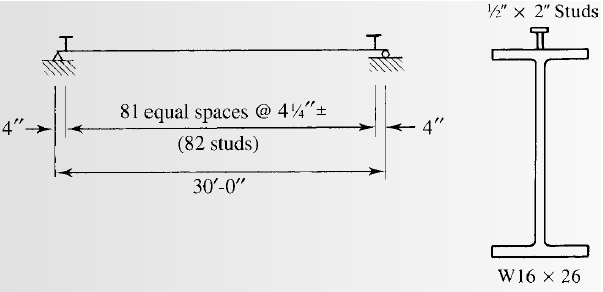
(c)
Selecting the stud anchors.
Answer to Problem 9.5.3P
we will use
Explanation of Solution
Calculation:
We have to check whether the studs satisfy the ASIC specifications.
From AISC specifications the maximum stud diameter will be equal to
Where,
Substitute the values in the equation, we get
Try for,
The area of stud using the following equation as follows:
Where, the diameter of the stud is d.
Substitute
We have the modulus of elasticity of concrete as follows:
Where, the modulus of elasticity of concrete is
unit weight of concrete is
the 28-day compressive strength of concrete is
Substitute
Calculating the shear strength of stud with the following formula:
Substitute the values, we get
Now, the upper limit of the shear strength is as follows:
As, the calculated value is less than the upper limit given by AISC, take the shear strength as:
The number of studs required for the half beam are as follows:
Substitute the values, we have
The number of studs required are as follows:
Substitute the values, we have
Calculate the spacing of the studs as following :
The minimum longitudinal spacing for the studs will be as follows:
Where, the minimum longitudinal spacing for the studs is
Substitute the values, we have
The minimum transversal spacing for the studs will be as follows:
Where, the minimum transversal spacing for the studs is
Substitute the values, we have
The maximum longitudinal spacing for the studs will be as follows:
Where, the maximum longitudinal spacing for the studs is
Substitute the values, we have
Therefore, the upper limit of the spacing is 32 inches.
Calculating the spacing for a stud at each section by the following formula:
Where, S is the spacing required
Calculating the spacing for two studs at each section by the following formula:
Where, S is the spacing required for two studs.
Conclusion:
Therefore, we will use
Want to see more full solutions like this?
Chapter 9 Solutions
Steel Design (Activate Learning with these NEW titles from Engineering!)


- 1: Determine the vertical deflection at joint E and the horizontal displacement at joint C for the following truss. Assume Area = 400 mm2 and E = 200000 MPa 30 m B с 30 kN A E D 25, KN -5 m- -5 m- -5 m- -5 m- -20 m-arrow_forwardA cantilever beam ABC is loaded as shown in Figure 1. A is a fixed support. Assume E= 200 GPa and I = 200 x 10^6 mm^4. (a) Using the moment area method, determine the slope at B. (b) Using the conjugate beam method, determine the vertical deflection at B. (c) Using the virtual work method, determine the vertical deflection at C.arrow_forwardCompute for the stresses (initial, const and final stage) and check for compliance in NSCP provisions. Also compute the following: 1. Compute and check if the section is Uncracked, Transition or Cracked as per NSCP. 2. Compute for its flexural capacity and check if it could carry the given load. BEAM SECTION NOT TO SCALE 1400mm 300 $1098 400 */ 400*300* 300 200 300 100 ORIGINAL SECTION/PRECA CAST-IN-PLACE (CIP) PART PRECAST LOADING AT SERVICE M • 21 KN (DEAD LOAD ONLY) 21KN 4.75m 9.25m CIVEN DATA STRANDS: 12-02 AT 120KN/STRAND (GOMM FROM BOTTOM) 8-2 AT 120HN/STRAND (120mm FROM BOTTOM) fc 42.5 MPa (BEAM) fc 38 MPa (CIP) f'a = 80% or fa fp-1860 MPa ESTRANDS 1976Pa OONG 23.6/m³ LOES 1-8% Loss 18% APPLY 3M LIVE LOAD AT CONST. PHASEarrow_forward
- Please explain all your steps. Thank you.arrow_forward10000 Quizl:Design a grit chamber for a horizontal velocity 250 mm/s, minimum flow 5,000 m³/day, maximum 20,000 m³/day, average flow is 12,500m³/day, S.O.R= 0.017 m/s, For a parabolic channels A =2/3 WD, detention time = 1 min Q Ac == HxW vs for inorganic particles = SOR As = LxW As V=Qxt=LxWxH Z=CxW2 Q (m³/day) | Ac (m²) W (m) | Z (m)arrow_forwardCan you please explain how to draw the shear and moment diagrams. Thank you.arrow_forward
- Q2: Design an activated sludge process to treat a waste flow of 15000 m³/day with a BODs of 180 mg/L following primary treatment. The effluent BOD, and SS are to be 20 m mg/L. Assume Xr = 15000 mg/L, X = 2500 mg/L, 0c = 10 day, Y = 0.60, kd=0.05. Determine 1- the reactor volume, 2- the Sludge production rate, 3- the circulation rate, 4- the hydraulic retention time, and 5- the oxygen required? C₁-Ce C 1 XV = 1 +0.532 QxC₁₂ VXF F= - 1+r (1+0.1r)² = Qr= dt Өс Qx Xr-X V R = [= Q YQ(So-S) Oc dx XV 1+Kd0c O₂demand =1.47 (So-S)Q-[1.14Xr(Qw)] Qw total sludge production/X, S = BOD, effluent - 0.63 * SS Warrow_forwardمارت حولة ملانول 60 Design Deceleration tank and screen for W.W.T.P of flow-144000 m² day Design Data: D.T=1-3 min 1-3b, d=1-1.5 m 60 Design Data: velocity= 0.6: 1.5 m/sec . A-Qdfv=b.d, b=2d 233 Design Data: bars used circular of p= 1.5:3 cm. rec. of (1:2 cm) x (2:6 cm) spacing between bars 2.5:5.0 cm fine screen, 2.5 7.5 cm coarse screen Sloping angle on hz (6)=45:60 = depth of water depth in approaching channel=d = ⚫nbars nspacings +1 ⚫b=nbars xo+nspacings I spacing net inclined area = 2 Aapproach channel=nspacing. spacing. L. 1=d/ sin Check: = 1.13 C 2.56 1134(6.05 P. 45.30 *velocity just befor the screen=v₁ = Qa(m³/sec) screen-b.d ≥ 0.6 m/sec. * velocity through the screen=v2 16mm use 2 Qa(m³/sec) nscreens (spacings Spacing).d ≤1.5 m/sec IsP. 22-65 12²² head losses = Ah = 1.4 x ≤0.1 m 2g bav usp = Ubar Q 23.65 k 148.72arrow_forwardCan you please explain the steps of this problem especially the variables for Q when solving for the shear force? Thanks.arrow_forward
- Please show all your steps. Thank you.arrow_forwardThe solution to this problem is 10.5kip. Please explain all the steps.arrow_forwardQ1: Design of trickling filter system single-stage with 3m depth, effluent BOD, of 20 mg/l, influent BODs =250mg/l, flow = 2.63 m³/min and hydraulic flow rate or hydraulic loading rate 25 m/day, r=3arrow_forward
 Steel Design (Activate Learning with these NEW ti...Civil EngineeringISBN:9781337094740Author:Segui, William T.Publisher:Cengage Learning
 Materials Science And Engineering PropertiesCivil EngineeringISBN:9781111988609Author:Charles GilmorePublisher:Cengage Learning
 Construction Materials, Methods and Techniques (M...Civil EngineeringISBN:9781305086272Author:William P. Spence, Eva KultermannPublisher:Cengage Learning
 Architectural Drafting and Design (MindTap Course...Civil EngineeringISBN:9781285165738Author:Alan Jefferis, David A. Madsen, David P. MadsenPublisher:Cengage Learning
 Fundamentals Of Construction EstimatingCivil EngineeringISBN:9781337399395Author:Pratt, David J.Publisher:Cengage,
 Traffic and Highway EngineeringCivil EngineeringISBN:9781305156241Author:Garber, Nicholas J.Publisher:Cengage Learning