
Concept explainers
Videos
(a) Show that the beam of Prob. 8.41 cannot be moved if the top surface of the dolly is slightly lower than the platform. (b) Show that the beam can be moved if two 175-lb workers stand on the beam at B, and determine how far to the left the beam can be moved.
8.41 A 10-ft beam, weighing 1200 lb, is to be moved to the left onto the platform as shown. A horizontal force P is applied to the dolly, which is mounted on frictionless wheels. The coefficients of friction between all surfaces are μs = 0.30 and μs = 0.25, and initially, χ = 2 ft. Knowing that the top surface of the dolly is slightly higher than the platform, determine the force P required to start moving the beam. (Hint: The beam is supported at A and D.)
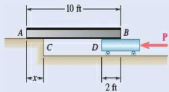
Fig. P8.41
(a)
Show that the beam cannot be moved if the top surface of the dolly is slightly lower than the platform.
Explanation of Solution
Given information:
The length of the beam is 10 ft.
The weight of the beam is
The coefficient of static friction between the surfaces is
The coefficient of kinetic friction between the surfaces is
Calculation:
Show the free-body diagram of the beam AB as in Figure 1.
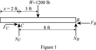
Find the normal force at point B by taking moment about end C.
Find the normal force at point C by resolving the vertical component of forces.
Find the maximum friction force at point C
Substitute 0.30 for
Find the maximum friction force at point B
Substitute 0.30 for
The maximum friction force at point B is less than the maximum friction force at point C.
The sliding is about to happen at point B.
Therefore, the beam
(b)
Show that the beam can be moved if two 175-lb workers stand on the beam at B.
Find the distance the beam moves to the left.
Answer to Problem 8.42P
The distance the beam moves to the left is
Explanation of Solution
Given information:
The length of the beam is 10 ft.
The weight of the beam is
The coefficient of static friction between the surfaces is
The coefficient of kinetic friction between the surfaces is
Calculation:
Show the free-body diagram of the beam AB as in Figure 2.
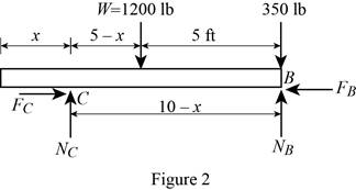
Find the normal force at point B by taking moment about end C.
Find the normal reaction at point C by taking moment about point B.
When two 175 lb workers stand on the end B:
Substitute 2 ft for x in Equation (1).
Substitute 2 ft for x in Equation (2).
Find the maximum friction force at point C
Substitute 0.30 for
Find the maximum friction force at point B
Substitute 0.30 for
The maximum friction force at point B is greater than the maximum friction force at point C.
The sliding is about to happen at point C.
Therefore, the beam
The beam will stop moving when the friction force at point C is equal to the maximum friction force at point B.
Find the friction force at point C
Substitute 0.25 for
Find the maximum friction force at point B
Substitute 0.30 for
Substitute
Therefore, the distance the beam moves to the left is
Want to see more full solutions like this?
Chapter 8 Solutions
VECTOR MECH...,STAT.+DYNA.(LL)-W/ACCESS


- Draw left view of the first orthographic projectionarrow_forwardSketch and Describe a timing diagram for a 2 stroke diesel engine emphasis on the 2 stroke as my last answer explained 4 stroke please include a diagram or sketch.arrow_forwardA 4 ft 200 Ib 1000 Ib.ft C 2 ft 350 Ib - за в 2.5 ft 150 Ib 250 Ib 375 300 Ib Replace the force system acting on the frame. shown in the figure by a resultant force (magnitude and direction), and specify where its line of action intersects member (AB), measured from point (A).arrow_forward
- A continuous flow calorimeter was used to obtain the calorific value of a sample of fuel and the following data collected: Mass of fuel: 2.25 kgInlet water temperature: 11 ° COutlet water temperature 60 ° CQuantity of water: 360 Liters Calorimeter efficiency: 85%Calculate the calorific value of the sample ( kJ / kg ). ive submitted this question twice and have gotten two way different answers. looking for some help thanksarrow_forward15 kg of steel ball bearings at 100 ° C is immersed in 25 kg of water at 20 ° C . Assuming no loss of heat to or from the container, calculate the final temperature of the water after equilibrium has been attained.Specific heat of steel: 0.4857 kJ / kg / ° KSpecific heat of water: 4.187 kJ / kg / ° Karrow_forwardSketch and explain a PV Diagram and a Temperature Entropy Diagram for a 4 stroke diesel enginearrow_forward
- A continuous flow calorimeter was used to obtain the calorific value of a sample of fuel and the following data collected: Mass of fuel: 2.25 kgInlet water temperature: 11 ° COutlet water temperature 60 ° CQuantity of water: 360 Liters Calorimeter efficiency: 85%Calculate the calorific value of the sample ( kJ / kg ).arrow_forwardChapter 12 - Lecture Notes.pptx: (MAE 272-01) (SP25) DY... Scoresarrow_forwardmylabmastering.pearson.com Chapter 12 - Lecture Notes.pptx: (MAE 272-01) (SP25) DY... P Pearson MyLab and Mastering Scoresarrow_forwardanswer the fallowing Brake Specific Fuel Consumption - 0.3 kg/kwh, Mechanical Efficiency- 90% Calorific Value of Fuel -45 MJ/kg. Given these values, find the indicated power, indicated thermal efficiency and brake thermal efficiencyarrow_forwardProblem 6. The circular plate shown rotates about its vertical diameter. At the instant shown, the angular velocity ₁ of the plate is 10 rad/s and is decreasing at the rate of 25 rad/s². The disk lies in the XY plane and Point D of strap CD moves upward. The relative speed u of Point D of strap CD is 1.5 m/s and is decreasing at the rate of 3 m/s². Determine (a) the velocity of D, (b) the acceleration of D. Answers: =0.75 +1.299]-1.732k m/s a=-28.6 +3.03-10.67k m/s² 200 mm x Zarrow_forwardProblem 1. The flywheel A has an angular velocity o 5 rad/s. Link AB is connected via ball and socket joints to the flywheel at A and a slider at B. Find the angular velocity of link AB and the velocity of slider B at this instant. (Partial Answer: @ABN = -2î + 2.25; red Z -1.2 ft C -7 Y -1.5 ft- B 2.0 ftarrow_forwardarrow_back_iosSEE MORE QUESTIONSarrow_forward_iosRecommended textbooks for you
 Elements Of ElectromagneticsMechanical EngineeringISBN:9780190698614Author:Sadiku, Matthew N. O.Publisher:Oxford University Press
 Mechanics of Materials (10th Edition)Mechanical EngineeringISBN:9780134319650Author:Russell C. HibbelerPublisher:PEARSON
 Thermodynamics: An Engineering ApproachMechanical EngineeringISBN:9781259822674Author:Yunus A. Cengel Dr., Michael A. BolesPublisher:McGraw-Hill Education
 Control Systems EngineeringMechanical EngineeringISBN:9781118170519Author:Norman S. NisePublisher:WILEY
 Mechanics of Materials (MindTap Course List)Mechanical EngineeringISBN:9781337093347Author:Barry J. Goodno, James M. GerePublisher:Cengage Learning
 Engineering Mechanics: StaticsMechanical EngineeringISBN:9781118807330Author:James L. Meriam, L. G. Kraige, J. N. BoltonPublisher:WILEY
Elements Of ElectromagneticsMechanical EngineeringISBN:9780190698614Author:Sadiku, Matthew N. O.Publisher:Oxford University PressMechanics of Materials (10th Edition)Mechanical EngineeringISBN:9780134319650Author:Russell C. HibbelerPublisher:PEARSONThermodynamics: An Engineering ApproachMechanical EngineeringISBN:9781259822674Author:Yunus A. Cengel Dr., Michael A. BolesPublisher:McGraw-Hill EducationControl Systems EngineeringMechanical EngineeringISBN:9781118170519Author:Norman S. NisePublisher:WILEYMechanics of Materials (MindTap Course List)Mechanical EngineeringISBN:9781337093347Author:Barry J. Goodno, James M. GerePublisher:Cengage LearningEngineering Mechanics: StaticsMechanical EngineeringISBN:9781118807330Author:James L. Meriam, L. G. Kraige, J. N. BoltonPublisher:WILEY