
Bundle: Mechanics Of Materials, Loose-leaf Version, 9th + Mindtap Engineering, 1 Term (6 Months) Printed Access Card
9th Edition
ISBN: 9781337594318
Author: Barry J. Goodno; James M. Gere
Publisher: Cengage Learning
expand_more
expand_more
format_list_bulleted
Concept explainers
Videos
Textbook Question
Chapter 8, Problem 8.3.13P
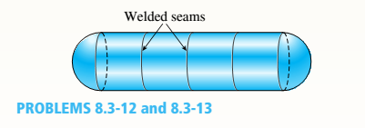
: A cylindrical tank with diameter d = 18 in, is subjected to internal gas pressure p = 450 psi. The tank is constructed of steel sections that arc welded circum fereiitially (sec figure). The heads of the tank are hemispherical. The allowable tensile and shear stresses are 8200 psi and 3000 psi, respectively. Also, the allowable tensile stress perpendicular to a weld is 6250 psi.
Determine the minimum required thickness /minof (a) the cylindrical part of the tank and (b) the hemispherical heads.
Expert Solution & Answer
Want to see the full answer?
Check out a sample textbook solution
Students have asked these similar questions
The state of stress at a point is σ = -4.00 kpsi, σy = 16.00 kpsi, σ = -14.00 kpsi, Try = 11.00 kpsi,
Tyz = 8.000 kpsi, and T = -14.00 kpsi.
Determine the principal stresses.
The principal normal stress σ₁ is determined to be [
The principal normal stress σ2 is determined to be [
The principal normal stress σ3 is determined to be
kpsi.
kpsi.
The principal shear stress 71/2 is determined to be [
The principal shear stress 7½ is determined to be [
The principal shear stress T₁/, is determined to be [
kpsi.
kpsi.
kpsi.
kpsi.
Repeat Problem 28, except using a shaft that is rotatingand transmitting a torque of 150 N * m from the left bearing to the middle of the shaft. Also, there is a profile keyseat at the middle under the load.
(I want to understand this problem)
Prob 2.
The material distorts into the dashed position
shown. Determine the average normal strains &x, Ey
and the shear strain Yxy at A, and the average
normal strain along line BE.
50 mm
B
200 mm
15 mm
30 mm
D
ΕΙ
50 mm
x
A
150 mm
F
Chapter 8 Solutions
Bundle: Mechanics Of Materials, Loose-leaf Version, 9th + Mindtap Engineering, 1 Term (6 Months) Printed Access Card
Ch. 8 - A spherical balloon is filled with a gas. The...Ch. 8 - A spherical balloon with an outer diameter of 500...Ch. 8 - A large spherical tank (see figure) contains gas...Ch. 8 - Solve the preceding problem if the internal...Ch. 8 - A hemispherical window (or viewport) in a...Ch. 8 - A rubber ball (sec figure) is inflated to a...Ch. 8 - (a) Solve part (a) of the preceding problem if the...Ch. 8 - A spherical steel pressure vessel (diameter 500...Ch. 8 - A spherical tank of diameter 48 in. and wall...Ch. 8 - Solve the preceding problem for the following...
Ch. 8 - A spherical stainless-steel tank having a diameter...Ch. 8 - Solve the preceding problem if the diameter is 480...Ch. 8 - : A hollow, pressurized sphere having a radius r =...Ch. 8 - A fire extinguisher tank is designed for an...Ch. 8 - Prob. 8.3.2PCh. 8 - A scuba t a n k (see fig ure) i s bci ng d e...Ch. 8 - A tall standpipc with an open top (see figure) has...Ch. 8 - An inflatable structure used by a traveling circus...Ch. 8 - A thin-walled cylindrical pressure vessel of a...Ch. 8 - A strain gage is installed in the longitudinal...Ch. 8 - A circular cylindrical steel tank (see figure)...Ch. 8 - A cylinder filled with oil is under pressure from...Ch. 8 - Solve the preceding problem if F =90 mm, F = 42...Ch. 8 - A standpipe in a water-supply system (see figure)...Ch. 8 - A cylindrical tank with hemispherical heads is...Ch. 8 - : A cylindrical tank with diameter d = 18 in, is...Ch. 8 - A pressurized steel tank is constructed with a...Ch. 8 - Solve the preceding problem for a welded Tank with...Ch. 8 - A wood beam with a cross section 4 x 6 in. is...Ch. 8 - Prob. 8.4.2PCh. 8 - A simply supported beam is subjected to two point...Ch. 8 - A cantilever beam with a width h = 100 mm and...Ch. 8 - A beam with a width h = 6 in. and depth h = 8 in....Ch. 8 - Beam ABC with an overhang BC is subjected to a...Ch. 8 - A cantilever beam(Z, = 6 ft) with a rectangular...Ch. 8 - Solve the preceding problem for the following...Ch. 8 - A simple beam with a rectangular cross section...Ch. 8 - An overhanging beam ABC has a guided support at A,...Ch. 8 - Solve the preceding problem if the stress and...Ch. 8 - A cantilever wood beam with a width b = 100 mm and...Ch. 8 - . A cantilever beam (width b = 3 in. and depth h =...Ch. 8 - A beam with a wide-flange cross section (see...Ch. 8 - A beam with a wide-flange cross section (see...Ch. 8 - A W 200 x 41.7 wide-flange beam (see Table F-l(b),...Ch. 8 - A W 12 x 35 steel beam is fixed at A. The beam has...Ch. 8 - A W 360 x 79 steel beam is fixed at A. The beam...Ch. 8 - A W 12 X 14 wide-flange beam (see Table F-l(a),...Ch. 8 - A cantilever beam with a T-section is loaded by an...Ch. 8 - Beam A BCD has a sliding support at A, roller...Ch. 8 - , Solve the preceding problem using the numerical...Ch. 8 - A W 12 x 35 steel cantilever beam is subjected to...Ch. 8 - A W 310 x 52 steel beam is subjected to a point...Ch. 8 - A solid circular bar is fixed at point A. The bar...Ch. 8 - A cantilever beam with a width h = 100 mm and...Ch. 8 - Solve the preceding problem using the following...Ch. 8 - A cylindrical tank subjected to internal...Ch. 8 - A cylindrical pressure vessel having a radius r =...Ch. 8 - A pressurized cylindrical tank with flat ends is...Ch. 8 - A cylindrical pressure vessel with flat ends is...Ch. 8 - The tensional pendulum shown in the figure...Ch. 8 - The hollow drill pipe for an oil well (sec figure)...Ch. 8 - Solve the preceding problem if the diameter is 480...Ch. 8 - . A segment of a generator shaft with a hollow...Ch. 8 - A post having a hollow, circular cross section...Ch. 8 - A sign is supported by a pole of hollow circular...Ch. 8 - A sign is supported by a pipe (see figure) having...Ch. 8 - A traffic light and signal pole is subjected to...Ch. 8 - Repeat the preceding problem but now find the...Ch. 8 - A bracket ABCD having a hollow circular cross...Ch. 8 - A gondola on a ski lift is supported by two bent...Ch. 8 - Beam A BCD has a sliding support at A, roller...Ch. 8 - A double-decker bicycle rack made up of square...Ch. 8 - A semicircular bar AB lying in a horizontal plane...Ch. 8 - Repeat Problem 8.5-22 but replace the square tube...Ch. 8 - An L-shaped bracket lying in a horizontal plane...Ch. 8 - A horizontal bracket ABC consists of two...Ch. 8 - , An arm A BC lying in a horizontal plane and...Ch. 8 - A crank arm consists of a solid segment of length...Ch. 8 - A moveable steel stand supports an automobile...Ch. 8 - A mountain bike rider going uphill applies a force...Ch. 8 - Determine the maximum tensile, compressive, and...Ch. 8 - Prob. 8.5.32PCh. 8 - A plumber's valve wrench is used to replace valves...Ch. 8 - A compound beam ABCD has a cable with force P...Ch. 8 - A steel hanger bracket ABCD has a solid, circular...
Knowledge Booster


Learn more about
Need a deep-dive on the concept behind this application? Look no further. Learn more about this topic, mechanical-engineering and related others by exploring similar questions and additional content below.Similar questions
- Prob 3. The triangular plate is fixed at its base, and its apex A is given a horizontal displacement of 5 mm. Determine the shear strain, Yxy, at A. Prob 4. The triangular plate is fixed at its base, and its apex A is given a horizontal displacement of 5 mm. Determine the average normal strain & along the x axis. Prob 5. The triangular plate is fixed at its base, and its apex A is given a horizontal displacement of 5 mm. Determine the average normal strain &x along the x' axis. x' 45° 800 mm 45° 45% 800 mm 5 mmarrow_forwardAn airplane lands on the straight runaway, originally travelling at 110 ft/s when s = 0. If it is subjected to the decelerations shown, determine the time t' needed to stop the plane and construct the s -t graph for the motion. draw a graph and show all work step by steparrow_forwarddny dn-1y dn-1u dn-24 +a1 + + Any = bi +b₂- + +bnu. dtn dtn-1 dtn-1 dtn-2 a) Let be a root of the characteristic equation 1 sn+a1sn- + +an = : 0. Show that if u(t) = 0, the differential equation has the solution y(t) = e\t. b) Let к be a zero of the polynomial b(s) = b₁s-1+b2sn−2+ Show that if the input is u(t) equation that is identically zero. = .. +bn. ekt, then there is a solution to the differentialarrow_forward
- B 60 ft WAB AB 30% : The crane's telescopic boom rotates with the angular velocity w = 0.06 rad/s and angular acceleration a = 0.07 rad/s². At the same instant, the boom is extending with a constant speed of 0.8 ft/s, measured relative to the boom. Determine the magnitude of the acceleration of point B at this instant.arrow_forwardThe motion of peg P is constrained by the lemniscate curved slot in OB and by the slotted arm OA. (Figure 1) If OA rotates counterclockwise with a constant angular velocity of 0 = 3 rad/s, determine the magnitude of the velocity of peg P at 0 = 30°. Express your answer to three significant figures and include the appropriate units. Determine the magnitude of the acceleration of peg P at 0 = 30°. Express your answer to three significant figures and include the appropriate units. 0 (4 cos 2 0)m² B Aarrow_forward5: The structure shown was designed to support a30-kN load. It consists of a boom AB with a 30 x 50-mmrectangular cross section and a rod BC with a 20-mm-diametercircular cross section. The boom and the rod are connected bya pin at B and are supported by pins and brackets at A and C,respectively.1. Calculate the normal stress in boom AB and rod BC,indicate if in tension or compression.2. Calculate the shear stress of pins at A, B and C.3. Calculate the bearing stresses at A in member AB,and in the bracket.arrow_forward
- 4: The boom AC is a 4-in. square steel tube with a wallthickness of 0.25 in. The boom is supported by the 0.5-in.-diameter pinat A, and the 0.375-in.-diameter cable BC. The working stresses are 25ksi for the cable, 18 ksi for the boom, and 13.6 ksi for shear in the pin.Neglect the weight of the boom.1. Calculate the maximum value of P (kips) based on boom compression and the maximum value of P (kips) based on tension in the cable.2. Calculate the maximum value of P (kips) based on shear in pin.arrow_forward3: A steel strut S serving as a brace for a boat hoist transmits a compressive force P = 54 kN to the deck of a pier as shown in Fig. STR-08. The strut has a hollow square cross section with a wall thickness t =12mm and the angle θ between the strut and the horizontal is 40°. A pin through the strut transmits the compressive force from the strut to two gusset plates G that are welded to the base plate B. Four anchor bolts fasten the base plate to the deck. The diameter of the pin is 20mm, the thickness of the gusset plates is 16mm, the thickness of the base plate is 8mm, and the diameter of the anchor bolts is 12mm. Disregard any friction between the base plate and the deck.1. Determine the shear stress in the pin, in MPa and the shear stress in the anchor bolts, in MPa.2. Determine the bearing stress in the strut holes, in MPa.arrow_forward1. In the figure, the beam, W410x67, with 9 mm web thicknesssubjects the girder, W530x109 with 12 mm web thickness to a shear load,P (kN). 2L – 90 mm × 90 mm × 6 mm with bolts frame the beam to thegirder.Given: S1 = S2 = S5 = 40 mm; S3 = 75 mm; S4 = 110 mmAllowable Stresses are as follows:Bolt shear stress, Fv = 125 MPaBolt bearing stress, Fp = 510 MPa1. Determine the allowable load, P (kN), based on the shearcapacity of the 4 – 25 mm diameter bolts (4 – d1) and calculate the allowable load, P (kN), based on bolt bearing stress on the web of the beam.2. If P = 450 kN, determine the minimum diameter (mm) of 4 – d1based on allowable bolt shear stress and bearing stress of thebeam web.arrow_forward
- 6: The 6-kN load P is supported by two wooden members of 75 x 125-mm uniform cross section that are joined by the simple glued scarf splice shown.1. Calculate the normal stress in the glue, in MPa.2. Calculate the shear stress in the glue, in MPa.arrow_forwardUsing Matlab calculate the following performance characteristics for a Tesla Model S undergoing the 4506 drive cycle test Prated Trated Ebat 80kW 254 Nm 85kWh/1645kg MUEH A rwheel 0.315M 133.3 C 0.491 Ng ng 7g 8.190.315 8.19 0.315 7ed= 85% Ebpt 35-956 DRIVE AXLE Ebfb chę =85% V Minverter H/A Battery Charger En AC Pry 9) required energy output from the motor to drive this cycle Cassume no regenerative braking) b) range of the Tesla Model S for this drive cycle (assume no regenerative breaking c) estimated mpge cycle of the Tesla Model S for this drive Cassume no regenerative breaking) d) Recalculate parts abc now assuming you can regenerate returns correctly due to inefficiency. from braking. Be careful to handle the diminishing energy braking makes in terms of required e) Quantify the percentage difference that regenerative required energy, range and mpge, DI L Ta a ra OLarrow_forwardHW.5.1 Determine the vertical displacement of joint C on the truss as shown by using Castigliano's theorem. Let E = 200(109) GPa and A = 300 mm² 4 m E 20 kN 3 m 3 m B D 30 kN Carrow_forward
arrow_back_ios
SEE MORE QUESTIONS
arrow_forward_ios
Recommended textbooks for you
 Mechanics of Materials (MindTap Course List)Mechanical EngineeringISBN:9781337093347Author:Barry J. Goodno, James M. GerePublisher:Cengage Learning
Mechanics of Materials (MindTap Course List)
Mechanical Engineering
ISBN:9781337093347
Author:Barry J. Goodno, James M. Gere
Publisher:Cengage Learning
Pressure Vessels Introduction; Author: Engineering and Design Solutions;https://www.youtube.com/watch?v=Z1J97IpFc2k;License: Standard youtube license