Concept explainers
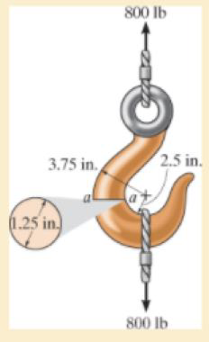
If it supports a cable loading of 800 lb, determine the maximum normal stress at section a–a and sketch the stress distribution acting over the cross section. Use the curved-beam formula to calculate the bending stress.

The maximum tensile stress
The maximum compressive stress
To sketch:
The stress distribution over the cross section.
Answer to Problem 8.1RP
The maximum tensile stress
The maximum compressive stress
Explanation of Solution
Given information:
The force in the cable is 800 lb.
Diameter of the circular is 1.25 in.
Calculation:
Expression to find the location of neutral
Here, R is the location of neutral axis, A is the cross sectional area of the member, r is the arbitrary position, and
Determine the radius
Here, d is the diameter of the circular cross section.
Substitute 1.25 in. for d in Equation (2).
Determine the area
Here, r is the radius of the circular cross section.
Substitute 0.625 in. for r in Equation (3).
Determine the value of
Here, c is the radius of cross section and
Find the distance measured from the center of curvature to the centroid of the cross section
Substitute 0.625 in. for c and 3.125 in. for
Substitute
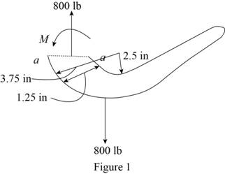
Sketch the cross section of eye hook as shown in Figure 1.

Let the moment acting at the section be M.
Express to the value of M as shown below:
Here, F is the load and R is the radius.
Determine the bending stress
Here, M is the applied moment and P is the applied load.
Substitute
Determine the maximum tensile stress
Hence, the maximum tensile stress
Determine the maximum compressive stress
Substitute
Hence, the maximum compressive stress
Sketch the stress distribution (tensile and compressive stress) along the cross section as shown in Figure 2.

Want to see more full solutions like this?
Chapter 8 Solutions
MECHANICS OF MATERIALS (LOOSE)-W/ACCESS
- 4. G A micarta pinion rotating at 1200 r.p.m. is to transmit 1 kW to a cast iron gear at a speed of 192 r.p.m. Assuming a starting overload of 20% and using 20° full depth involute teeth, determine the module, number of teeth on the pinion and gear and face width. Take allowable static strength for micarta as 40 MPa and for cast iron as 53 MPa. Check the pair in wear.arrow_forwardI want to solve these choicesarrow_forward2. A spur gear made of bronze drives a mid steel pinion with angular velocity ratio of 32: 1. The pressure angle is 14½. It transmits 5 kW at 1800 r.p.m. of pinion. Considering only strength, design the smallest diameter gears and find also necessary face width. The number of teeth should not be less than 15 teeth on either gear. The elastic strength of bronze may be taken as 84 MPa and of steel as 105 MPa. Lewis factor for 14½½ pressure angle may be taken 0.684 0.124 y = No. of teeth as [Ans. m 3 mm; b= 35 mm; Dp = 48 mm; D= 168 mm]arrow_forward
- Q2. Determine the safety factors for the bracket rod shown in Figure 2 based on both the distortion-energy theory and the maximum shear theory and compare them. Given: The material is 2024-T4 aluminum with a yield strength of 47 000 psi. The rod length /= 6 in. and arm a = 8 in. The rod outside diameter od 1.5 in., id = 1 in, h=2 in., t=0.5 in., Load F= 1000 lb. Assumptions: The load is static and the assembly is at room temperature. Consider shear due to transverse loading as well as other stresses. (Note: solve in SI units) wall tube Figure 2 armarrow_forwardThe question has been set up with all the cuts needed to accurately derive expressions for V(x) and M(x). Using the cuts free body diagrams set up below, derive expressions for V(x) and M(x). If you use the method of cuts then validate your answers using calculus or vice versa.arrow_forwardIt is required to treat 130 kmol/hr of chloroform-air feed gas mixture that contains 12% chloroform. It is required to remove 93% of chloroform using 150 kmol/hr of solvent that contains 99.6% water and 0.4% chloroform. The cross sectional area of the column is 0.8 m². Calculate the column height using the following data; kx'.a = 1.35 (kmol/m³.s (Ax)), and ky'.a = 0.06 (kmol/m³.s (Ay)), kx/ky = 1.35, and the equilibrium data are: X 0 0.0133 0.033 y 0 0.01 0.0266 0.049 0.064 0.0747 0.0933 0.1053 0.0433 0.06 0.0733 0.111 0.1 0.12 0.14arrow_forward
- ४ B: Find the numerical solution for the 2D equation below and calculate the temperature values for each grid point shown in Fig. 2 (show all steps). (Do only one trail using following initial values and show the final matrix) [T1] T₂ T3 [T] 1 = [0] 0 0 d dx dx) (ka)+4(ka) = dy -20xy, k = 1 + 0.3 T ge L=3cm, 4x= Ay B.Cs.: at x=0=LT=0°C at y=0-L T=10°C Fig. (2)arrow_forward: +0 العنوان use only Two rods fins) having same dimensions, one made orass (k = 85 Wm K) and the mer of copper (k = 375 W/m K), having of their ends inserted into a furna. At a section 10.5 cm a way from furnace, the temperature of brass rod 120 Find the distance at which the ame temperature would be reached in the per rod ? both ends are ex osed to the same environment. ns 2.05 ۲/۱ ostrararrow_forwardFor the beam show below, draw A.F.D, S.F.D, B.M.D 6 kN/m 1 M B. 3 M Marrow_forward
- 1. Two long rods of the same diameter-one made of brass (k=85w/m.k) and the other made of copper (k=375 w/m.k) have one of their ends inserted into a furnace (as shown in the following figure). Both rods are exposed to the same environment. At a distance of 105 mm from the furnace, the temperature of the brass rod is 120°C. At what distance from the furnace will the same temperature be reached in the copper rod? Furnace 105 mm T₁ Brass rod ⑪ h Too- x2- Ti Copper rodarrow_forward: +0 العنوان use only Two rods fins) having same dimensions, one made orass (k = 85 Wm K) and the mer of copper (k = 375 W/m K), having of their ends inserted into a furna. At a section 10.5 cm a way from furnace, the temperature of brass rod 120 Find the distance at which the ame temperature would be reached in the per rod ? both ends are ex osed to the same environment. ns 2.05 ۲/۱ ostrararrow_forwardمشر on ۲/۱ Two rods (fins) having same dimensions, one made of brass(k=85 m K) and the other of copper (k = 375 W/m K), having one of their ends inserted into a furnace. At a section 10.5 cm a way from the furnace, the temperature brass rod 120°C. Find the distance at which the same temperature would be reached in the copper rod ? both ends are exposed to the same environment. 22.05 ofthearrow_forward
 Mechanics of Materials (MindTap Course List)Mechanical EngineeringISBN:9781337093347Author:Barry J. Goodno, James M. GerePublisher:Cengage Learning
