
MECHANICS OF MATERIALS (LOOSE)-W/ACCESS
10th Edition
ISBN: 9780134583228
Author: HIBBELER
Publisher: PEARSON
expand_more
expand_more
format_list_bulleted
Concept explainers
Videos
Textbook Question
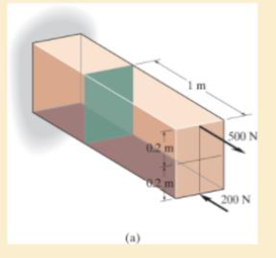
Chapter 8.2, Problem 8.1PP
Show the results on the left segment.
Expert Solution & Answer

Learn your wayIncludes step-by-step video

schedule11:00
Students have asked these similar questions
I keep trying this problem but cant seem to get the sheer right can you help me figure this out please?
The pillar crane is subjected to the crate having a mass of 1000 kgkg. The boom is held in position shown in (Figure 1).Determine the force in the tie rod ABAB.Determine the horizontal and vertical reactions at the pin support CC.
Problem 7.1
Part A
In (Figure 1), F₁ = 550 lb, F2 = 250 lb, and F3 = 340 lb.
Figure
F
F
B
Part B
Determine the shear force at point C.
Express your answer to three significant figures and include the appropriate units.
Vc=522
?
lb
Submit Previous Answers Request Answer
× Incorrect; Try Again; 15 attempts remaining
Part C
Determine the moment at point C.
Express your answer to three significant figures and include the appropriate units.
1 of 1
Mc = 1867
F
E
D
lb.ft
Submit
Previous Answers Request Answer
× Incorrect; Try Again; 24 attempts remaining
▸
Part D
6 ft-
4 ft-
4 ft-
6 ft
12 ft
Chapter 8 Solutions
MECHANICS OF MATERIALS (LOOSE)-W/ACCESS
Ch. 8.1 - If it is subjected to an internal pressure of p =...Ch. 8.1 - If it is subjected to an internal pressure of p =...Ch. 8.1 - The thin-walled cylinder can be supported in one...Ch. 8.1 - If the inner diameter of the tank is 22 in., and...Ch. 8.1 - Air pressure in the cylinder is increased by...Ch. 8.1 - Determine the maximum force P that can be exerted...Ch. 8.1 - A boiler is constructed of 8-mm-thick steel plates...Ch. 8.1 - 88. The steel water pipe has an inner diameter of...Ch. 8.1 - The steel water pipe has an inner diameter of 12...Ch. 8.1 - The A-36-steel band is 2 in. wide and is secured...
Ch. 8.1 - The gas pipe line is supported every 20 ft by...Ch. 8.1 - A pressure-vessel head is fabricated by welding...Ch. 8.1 - An A-36-steel hoop has an inner diameter of 23.99...Ch. 8.1 - The ring, having the dimensions shown, is placed...Ch. 8.1 - The inner ring A has an inner radius r1 and outer...Ch. 8.1 - Two hemispheres having an inner radius of 2 ft and...Ch. 8.1 - In order to increase the strength of the pressure...Ch. 8.2 - Show the results on the left segment.Ch. 8.2 - Show the stress that each of these loads produce...Ch. 8.2 - Fundamental Problems F81. Determine the normal...Ch. 8.2 - Show the results in a differential element at the...Ch. 8.2 - Determine the state of stress at point A on the...Ch. 8.2 - Determine the magnitude of the load P that will...Ch. 8.2 - Determine the state of stress at point B. Show the...Ch. 8.2 - Determine the state of stress at point A on the...Ch. 8.2 - Determine the state of stress at point A on the...Ch. 8.2 - Show the results in a differential element at the...Ch. 8.2 - Determine the shortest distance d to the edge of...Ch. 8.2 - The plate has a thickness of 20 mm and P acts...Ch. 8.2 - Plot the distribution of normal stress acting...Ch. 8.2 - Also, plot the normal-stress distribution over the...Ch. 8.2 - If the allowable normal stress for the steel is...Ch. 8.2 - If the applied force P = 1.50 kip, determine the...Ch. 8.2 - Determine the maximum normal stress on the cross...Ch. 8.2 - If the wood has an allowable normal stress of...Ch. 8.2 - Determine the maximum normal stress along section...Ch. 8.2 - Sketch the stress distribution along section aa of...Ch. 8.2 - Sketch the normal-stress distribution acting over...Ch. 8.2 - Determine the state of stress at points A and B,...Ch. 8.2 - If the force of 100 N is applied to the handles,...Ch. 8.2 - Determine the stress components at point A on the...Ch. 8.2 - Determine the stress components at point B on the...Ch. 8.2 - Determine the normal stress developed at points A...Ch. 8.2 - Sketch the normal-stress distribution acting over...Ch. 8.2 - Determine the state of stress at points A and B,...Ch. 8.2 - Determine the state of stress at point A on the...Ch. 8.2 - Determine the state of stress at point B on the...Ch. 8.2 - Determine the state of stress acting at point D....Ch. 8.2 - Determine the state of stress acting at point E....Ch. 8.2 - If it is subjected to the force system shown,...Ch. 8.2 - Solve Prob.840 for point B.Ch. 8.2 - Determine the stress components acting on the...Ch. 8.2 - Determine the stress components acting on the...Ch. 8.2 - Neglect the weight of the block.Ch. 8.2 - Neglect the weight of the block.Ch. 8.2 - He is supported uniformly by two bars, each having...Ch. 8.2 - Determine the state of stress at point A, and show...Ch. 8.2 - Determine the state of stress at point B, and show...Ch. 8.2 - Determine the state of stress at point C, and show...Ch. 8.2 - Determine the maximum radius e at which the load P...Ch. 8.2 - Specify the region to which this load can be...Ch. 8.2 - Determine the smallest force P that can be applied...Ch. 8.2 - The coiled spring is subjected to a force P. If we...Ch. 8.2 - The pins at C and D are at the same location as...Ch. 8.2 - Determine the state of stress at point A, and show...Ch. 8.2 - Determine the state of stress at point B, and show...Ch. 8.2 - Determine the stress components at points A and B...Ch. 8.2 - Determine the stress components at points C and D...Ch. 8.2 - Determine the stress components in the support...Ch. 8.2 - Determine the stress components in the support...Ch. 8.2 - If the force at the ram on the clamp at D is P= 8...Ch. 8.2 - Determine the maximum ram force P that can be...Ch. 8.2 - and an outer radius of 3.00 in. If the face of the...Ch. 8.2 - for points E and F.Ch. 8.2 - Determine the stress components at points A and B...Ch. 8.2 - Solve Prob.8-65 for points C and D.Ch. 8.2 - Due to internal gearing, this causes the block to...Ch. 8.2 - Determine the state of stress at point A and show...Ch. 8.2 - Solve Prob.868 for point B.Ch. 8.2 - Determine the stress components at point A. Sketch...Ch. 8.2 - for the stress components at point B.Ch. 8.2 - Determine the state of stress at point A at...Ch. 8.2 - Determine the state of stress at point B at...Ch. 8 - If it supports a cable loading of 800 lb,...Ch. 8 - Determine the state of stress at point E on the...Ch. 8 - Determine the state of stress at point F on the...Ch. 8 - The suspender arm AE has a square cross-sectional...Ch. 8 - If the cross section of the femur at section aa...Ch. 8 - If it has a mass of 5 kg/m, determine the largest...Ch. 8 - and is used to support the vertical reactions of...Ch. 8 - and is used to support the vertical reactions of...
Additional Engineering Textbook Solutions
Find more solutions based on key concepts
What is an inline member function?
Starting Out with C++ from Control Structures to Objects (9th Edition)
_____ are characters or symbols that perform operations on one or more operands.
Starting Out With Visual Basic (8th Edition)
What sequence of events do you think would be required to move the contents of one memory cell in a computer to...
Computer Science: An Overview (13th Edition) (What's New in Computer Science)
ShiftSupervisor Class In a particular factory, a shift supervisor is a salaried employee who supervises a shift...
Starting Out with Java: From Control Structures through Objects (7th Edition) (What's New in Computer Science)
For the circuit shown, use the node-voltage method to find v1, v2, and i1.
How much power is delivered to the c...
Electric Circuits. (11th Edition)
In Exercises 1 through 52, determine the output produced by the lines of code. DimlastName,message,firstNameAsS...
Introduction To Programming Using Visual Basic (11th Edition)
Knowledge Booster


Learn more about
Need a deep-dive on the concept behind this application? Look no further. Learn more about this topic, mechanical-engineering and related others by exploring similar questions and additional content below.Similar questions
- Sketch h, for Problem 13.64 13 13.65 In Sketch i the tension on the slack side of the left pulley is 20% of that on the tight side. The shaft rotates at 1000 rpm. Select a pair of deep-groove roller bearings to sup- port the shaft for 99% reliability and a life of 20,000 hr. Assume Eq. (13.83) can be used to account for lubricant cleanliness. All length dimensions are in millimeters. b Z 02 0 y 200 500. 187 100 30° B TONE 500 diam 800 N 650 diam 100 N Sketch i, for Problem 13.65 வarrow_forwardProblem 2: Consider the rectangular wood beam below. Use E=1.0. 1. Determine the slope at A. 2. Determine the largest deflection between A and B. Use the elastic curve equation. Show all work. (20%) 3 kN/m A 2.4 m - 50 mm AT 150 mm 0000 - B C 1.2 m→arrow_forwardPlease give a clear solution.arrow_forward
- USE MATLAB ONLY Turbomachienery . GIven: vx = 185 m/s, flow angle = 60 degrees, R = 0.5, U = 150 m/s, b2 = -a3, a2 = -b3 Find: velocity triangle , a. magnitude of abs vel leaving rotor (m/s) b. flow absolute angles (a1, a2, a3) 3. flow rel angles (b2, b3) d. specific work done e. use code to draw vel. diagram Use this code for plot % plots Velocity Tri. in Ch4 function plotveltri(al1,al2,al3,b2,b3) S1L = [0 1]; V1x = [0 0]; V1s = [0 1*tand(al3)]; S2L = [2 3]; V2x = [0 0]; V2s = [0 1*tand(al2)]; W2s = [0 1*tand(b2)]; U2x = [3 3]; U2y = [1*tand(b2) 1*tand(al2)]; S3L = [4 5]; V3x = [0 0]; V3r = [0 1*tand(al3)]; W3r = [0 1*tand(b3)]; U3x = [5 5]; U3y = [1*tand(b3) 1*tand(al3)]; plot(S1L,V1x,'k',S1L,V1s,'r',... S2L,V2x,'k',S2L,V2s,'r',S2L,W2s,'b',U2x,U2y,'g',... S3L,V3x,'k',S3L,V3r,'r',S3L,W3r,'b',U3x,U3y,'g',...... 'LineWidth',2,'MarkerSize',10),... axis([-1 6 -4 4]), ... title('Velocity Triangle'), ... xlabel('x'),ylarrow_forwardThe wall of a furnace has a thickness of 5 cm and thermal conductivity of 0.7 W/m-°C. The inside surface is heated by convection with a hot gas at 402°C and a heat transfer coefficient of 37 W/m²-°C. The outside surface has an emissivity of 0.8 and is exposed to air at 27°C with a heat transfer coefficient of 20 W/m²-ºC. Assume that the furnace is inside a large room with walls, floor and ceiling at 27°C. Show the thermal circuit and determine the heat flux through the furnace wall. h₁ T₁ k -L T. sur ho Earrow_forwardTurbomachienery . GIven: vx = 185 m/s, flow angle = 60 degrees, R = 0.5, U = 150 m/s, b2 = -a3, a2 = -b3 Find: velocity triangle , a. magnitude of abs vel leaving rotor (m/s) b. flow absolute angles (a1, a2, a3) 3. flow rel angles (b2, b3) d. specific work done e. use code to draw vel. diagram Use this code for plot % plots Velocity Tri. in Ch4 function plotveltri(al1,al2,al3,b2,b3) S1L = [0 1]; V1x = [0 0]; V1s = [0 1*tand(al3)]; S2L = [2 3]; V2x = [0 0]; V2s = [0 1*tand(al2)]; W2s = [0 1*tand(b2)]; U2x = [3 3]; U2y = [1*tand(b2) 1*tand(al2)]; S3L = [4 5]; V3x = [0 0]; V3r = [0 1*tand(al3)]; W3r = [0 1*tand(b3)]; U3x = [5 5]; U3y = [1*tand(b3) 1*tand(al3)]; plot(S1L,V1x,'k',S1L,V1s,'r',... S2L,V2x,'k',S2L,V2s,'r',S2L,W2s,'b',U2x,U2y,'g',... S3L,V3x,'k',S3L,V3r,'r',S3L,W3r,'b',U3x,U3y,'g',...... 'LineWidth',2,'MarkerSize',10),... axis([-1 6 -4 4]), ... title('Velocity Triangle'), ... xlabel('x'),ylabel('y'), gridarrow_forward
- To save fuel during the heating season it is suggested that glass windows be covered at night with a 1.2 cm layer of polystyrene. Estimate the percent savings in energy and discuss the feasibility of this idea. Show the thermal circuit with and without the insulation panel. Consider a typical case of 0.2 cm thick window glass with inside and outside heat transfer coefficients of 6 and 32 W/m²-ºC. Lg←←Lp h T₁ T。 g kp insulation panelarrow_forwardA plate of thickness L and thermal conductivity k is exposed to a fluid at temperature T1 with a heat transfer coefficient h, on one side and T2 and h₂ on the other side. Determine the one-dimensional temperature distribution in the plate. Assume steady state and constant conductivity. L h h T%2 k Tx1 0xarrow_forwardDetermine the heater capacity needed to maintain the inside temperature of a laboratory chamber at 38°C when placed in a room at 21°C. The chamber is cubical with each side measuring 35 cm. The walls are 1.2 cm thick and are made of polystyrene. The inside and outside heat transfer coefficients are 5 and 22 W/m²-°C.arrow_forward
- (a) Refer to the above figure .What kind of controller is it ? (b) simplify the block diagramto derive the closed loop transfer function of the system. (C) What are the assumptions thatare needed to make to findthe controller gain ? What arethe value of Kp , Ti and Td ?arrow_forwardLonsider a regenerative gas turbine power plant with two stages of compression and two stages of expansion. The compressor pressure ratio of the compressor is 3. Air enters each stage of compressor at 290 K and esch stage of turbine at 1400 K. The regetierator has an effectiveness of 100%, Determine (a) The enthalpy at stage#2 in KJ/kg (b) The enthalpy at stage in KJ/kg" (c) The cathalpy at stager in KJ/kg* (d) The enthalpy at stage#10 in KJ/kg (c) The mass flow rate of air needed to develop a net power output of 50 MW *For all final answers please enter the integer part only, (ie 1234) and do not include the decimal part and the decimal point No rounding in your calculationarrow_forwardConsider a regenerative gas turbine power plant with two stages of compression and two stages of expansion. The compressor pressure ratio of the compressor is 3. Air enters each stage of compressor at 290 K and each stage of turbine at 1400 K. The regenerator has an effectiveness of 100%. Determine (a) The enthalpy at stage#2 in KJ/kg⭑ (b) The enthalpy at stage#6 in KJ/kg* (c) The enthalpy at stage#9 in KJ/kg (d) The enthalpy at stage#10 in KJ/kg (e)The mass flow rate of air needed to develop a net power output of 50 MW* *For all final answers please enter the integer part only, (ie 1234) and do not include the decimal part and the decimal point No rounding in your calculation. Compressor stage 1 Regenerator www HX ww 9 Combustor Reheat Intercooler ww Compressor stage 2 Turbine 1 combustor Turbine 2arrow_forward
arrow_back_ios
SEE MORE QUESTIONS
arrow_forward_ios
Recommended textbooks for you
 Elements Of ElectromagneticsMechanical EngineeringISBN:9780190698614Author:Sadiku, Matthew N. O.Publisher:Oxford University Press
 Mechanics of Materials (10th Edition)Mechanical EngineeringISBN:9780134319650Author:Russell C. HibbelerPublisher:PEARSON
 Thermodynamics: An Engineering ApproachMechanical EngineeringISBN:9781259822674Author:Yunus A. Cengel Dr., Michael A. BolesPublisher:McGraw-Hill Education
 Control Systems EngineeringMechanical EngineeringISBN:9781118170519Author:Norman S. NisePublisher:WILEY
 Mechanics of Materials (MindTap Course List)Mechanical EngineeringISBN:9781337093347Author:Barry J. Goodno, James M. GerePublisher:Cengage Learning
 Engineering Mechanics: StaticsMechanical EngineeringISBN:9781118807330Author:James L. Meriam, L. G. Kraige, J. N. BoltonPublisher:WILEY
Elements Of Electromagnetics
Mechanical Engineering
ISBN:9780190698614
Author:Sadiku, Matthew N. O.
Publisher:Oxford University Press
Mechanics of Materials (10th Edition)
Mechanical Engineering
ISBN:9780134319650
Author:Russell C. Hibbeler
Publisher:PEARSON
Thermodynamics: An Engineering Approach
Mechanical Engineering
ISBN:9781259822674
Author:Yunus A. Cengel Dr., Michael A. Boles
Publisher:McGraw-Hill Education
Control Systems Engineering
Mechanical Engineering
ISBN:9781118170519
Author:Norman S. Nise
Publisher:WILEY
Mechanics of Materials (MindTap Course List)
Mechanical Engineering
ISBN:9781337093347
Author:Barry J. Goodno, James M. Gere
Publisher:Cengage Learning
Engineering Mechanics: Statics
Mechanical Engineering
ISBN:9781118807330
Author:James L. Meriam, L. G. Kraige, J. N. Bolton
Publisher:WILEY
LIMITS FITS AND TOLERANCES: What is limit fit & tolerance and its need? Animation; Author: ADTW learn;https://www.youtube.com/watch?v=joBy4BoJszo;License: Standard YouTube License, CC-BY
Limits and Continuity; Author: The Organic Chemistry Tutor;https://www.youtube.com/watch?v=9brk313DjV8;License: Standard YouTube License, CC-BY