
MECHANICS OF MATERIALS (LOOSE)-W/ACCESS
10th Edition
ISBN: 9780134583228
Author: HIBBELER
Publisher: PEARSON
expand_more
expand_more
format_list_bulleted
Concept explainers
Videos
Textbook Question
Chapter 8.2, Problem 8.41P
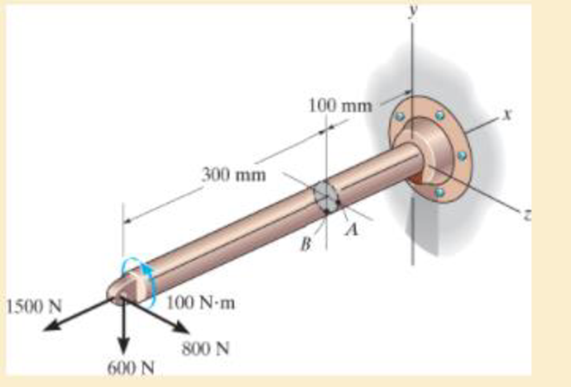
Solve Prob.8–40 for point B.
Expert Solution & Answer
Want to see the full answer?
Check out a sample textbook solution
Students have asked these similar questions
What would the electropneumatic diagram of a circuit with the sequence a+b+c+(a-b-c-) look like?
### What would the electropneumatic diagram of a circuit with the sequence a+b+c+(a-b-c-) look like, with a counter, in the fluidsim?
You are asked to design a unit to condense ammonia. The required condensation rate is 0.09kg/s. Saturated ammonia at 30 o C is passed over a vertical plate (10 cm high and 25 cm wide).The properties of ammonia at the saturation temperature of 30°C are hfg = 1144 ́10^3 J/kg andrv = 9.055 kg/m 3 . Use the properties of liquid ammonia at the film temperature of 20°C (Ts =10 o C):Pr = 1.463
rho_l= 610.2 kf/m^3
liquid viscosity= 1.519*10^-4 kg/ ms
kinematic viscosity= 2.489*10^-7 m^2/s
Cpl= 4745 J/kg C
kl=0.4927 W/m CCalculate the surface temperature required to achieve the desired condensation rate of 0.09 kg/s( should be 688 degrees C) a) Show that if you use a bigger vertical plate (2.5 m-wide and 0.8 m-height), the requiredsurface temperature would be now 20 o C. You may use all the properties given as an initialguess. No need to iterate to correct for Tf. b) What if you still want to use small plates because of the space constrains? One way to getaround this problem is to use small…
Chapter 8 Solutions
MECHANICS OF MATERIALS (LOOSE)-W/ACCESS
Ch. 8.1 - If it is subjected to an internal pressure of p =...Ch. 8.1 - If it is subjected to an internal pressure of p =...Ch. 8.1 - The thin-walled cylinder can be supported in one...Ch. 8.1 - If the inner diameter of the tank is 22 in., and...Ch. 8.1 - Air pressure in the cylinder is increased by...Ch. 8.1 - Determine the maximum force P that can be exerted...Ch. 8.1 - A boiler is constructed of 8-mm-thick steel plates...Ch. 8.1 - 88. The steel water pipe has an inner diameter of...Ch. 8.1 - The steel water pipe has an inner diameter of 12...Ch. 8.1 - The A-36-steel band is 2 in. wide and is secured...
Ch. 8.1 - The gas pipe line is supported every 20 ft by...Ch. 8.1 - A pressure-vessel head is fabricated by welding...Ch. 8.1 - An A-36-steel hoop has an inner diameter of 23.99...Ch. 8.1 - The ring, having the dimensions shown, is placed...Ch. 8.1 - The inner ring A has an inner radius r1 and outer...Ch. 8.1 - Two hemispheres having an inner radius of 2 ft and...Ch. 8.1 - In order to increase the strength of the pressure...Ch. 8.2 - Show the results on the left segment.Ch. 8.2 - Show the stress that each of these loads produce...Ch. 8.2 - Fundamental Problems F81. Determine the normal...Ch. 8.2 - Show the results in a differential element at the...Ch. 8.2 - Determine the state of stress at point A on the...Ch. 8.2 - Determine the magnitude of the load P that will...Ch. 8.2 - Determine the state of stress at point B. Show the...Ch. 8.2 - Determine the state of stress at point A on the...Ch. 8.2 - Determine the state of stress at point A on the...Ch. 8.2 - Show the results in a differential element at the...Ch. 8.2 - Determine the shortest distance d to the edge of...Ch. 8.2 - The plate has a thickness of 20 mm and P acts...Ch. 8.2 - Plot the distribution of normal stress acting...Ch. 8.2 - Also, plot the normal-stress distribution over the...Ch. 8.2 - If the allowable normal stress for the steel is...Ch. 8.2 - If the applied force P = 1.50 kip, determine the...Ch. 8.2 - Determine the maximum normal stress on the cross...Ch. 8.2 - If the wood has an allowable normal stress of...Ch. 8.2 - Determine the maximum normal stress along section...Ch. 8.2 - Sketch the stress distribution along section aa of...Ch. 8.2 - Sketch the normal-stress distribution acting over...Ch. 8.2 - Determine the state of stress at points A and B,...Ch. 8.2 - If the force of 100 N is applied to the handles,...Ch. 8.2 - Determine the stress components at point A on the...Ch. 8.2 - Determine the stress components at point B on the...Ch. 8.2 - Determine the normal stress developed at points A...Ch. 8.2 - Sketch the normal-stress distribution acting over...Ch. 8.2 - Determine the state of stress at points A and B,...Ch. 8.2 - Determine the state of stress at point A on the...Ch. 8.2 - Determine the state of stress at point B on the...Ch. 8.2 - Determine the state of stress acting at point D....Ch. 8.2 - Determine the state of stress acting at point E....Ch. 8.2 - If it is subjected to the force system shown,...Ch. 8.2 - Solve Prob.840 for point B.Ch. 8.2 - Determine the stress components acting on the...Ch. 8.2 - Determine the stress components acting on the...Ch. 8.2 - Neglect the weight of the block.Ch. 8.2 - Neglect the weight of the block.Ch. 8.2 - He is supported uniformly by two bars, each having...Ch. 8.2 - Determine the state of stress at point A, and show...Ch. 8.2 - Determine the state of stress at point B, and show...Ch. 8.2 - Determine the state of stress at point C, and show...Ch. 8.2 - Determine the maximum radius e at which the load P...Ch. 8.2 - Specify the region to which this load can be...Ch. 8.2 - Determine the smallest force P that can be applied...Ch. 8.2 - The coiled spring is subjected to a force P. If we...Ch. 8.2 - The pins at C and D are at the same location as...Ch. 8.2 - Determine the state of stress at point A, and show...Ch. 8.2 - Determine the state of stress at point B, and show...Ch. 8.2 - Determine the stress components at points A and B...Ch. 8.2 - Determine the stress components at points C and D...Ch. 8.2 - Determine the stress components in the support...Ch. 8.2 - Determine the stress components in the support...Ch. 8.2 - If the force at the ram on the clamp at D is P= 8...Ch. 8.2 - Determine the maximum ram force P that can be...Ch. 8.2 - and an outer radius of 3.00 in. If the face of the...Ch. 8.2 - for points E and F.Ch. 8.2 - Determine the stress components at points A and B...Ch. 8.2 - Solve Prob.8-65 for points C and D.Ch. 8.2 - Due to internal gearing, this causes the block to...Ch. 8.2 - Determine the state of stress at point A and show...Ch. 8.2 - Solve Prob.868 for point B.Ch. 8.2 - Determine the stress components at point A. Sketch...Ch. 8.2 - for the stress components at point B.Ch. 8.2 - Determine the state of stress at point A at...Ch. 8.2 - Determine the state of stress at point B at...Ch. 8 - If it supports a cable loading of 800 lb,...Ch. 8 - Determine the state of stress at point E on the...Ch. 8 - Determine the state of stress at point F on the...Ch. 8 - The suspender arm AE has a square cross-sectional...Ch. 8 - If the cross section of the femur at section aa...Ch. 8 - If it has a mass of 5 kg/m, determine the largest...Ch. 8 - and is used to support the vertical reactions of...Ch. 8 - and is used to support the vertical reactions of...
Knowledge Booster


Learn more about
Need a deep-dive on the concept behind this application? Look no further. Learn more about this topic, mechanical-engineering and related others by exploring similar questions and additional content below.Similar questions
- Homework#5arrow_forwardQuestion 1: Beam Analysis Two beams (ABC and CD) are connected using a pin immediately to the left of Point C. The pin acts as a moment release, i.e. no moments are transferred through this pinned connection. Shear forces can be transferred through the pinned connection. Beam ABC has a pinned support at point A and a roller support at Point C. Beam CD has a roller support at Point D. A concentrated load, P, is applied to the mid span of beam CD, and acts at an angle as shown below. Two concentrated moments, MB and Mc act in the directions shown at Point B and Point C respectively. The magnitude of these moments is PL. Moment Release A B с ° MB = PL Mc= = PL -L/2- -L/2- → P D Figure 1: Two beam arrangement for question 1. To analyse this structure, you will: a) Construct the free body diagrams for the structure shown above. When constructing your FBD's you must make section cuts at point B and C. You can represent the structure as three separate beams. Following this, construct the…arrow_forwardA differential element on the bracket is subjected to plane strain that has the following components:, Ɛx = 300 × 10-6, Ɛy = 150 × 10-6, Ɛxy = -750 x 10-6. Use the strain-transformation equations and determine the normal strain Ɛx in the X/ direction on an element oriented at an angle of 0 = 40°. Note, a positive angle, 0, is counter clockwise. x Enter your answer in micro strain to a precision of two decimal places. eg. if your answer is 300.15X10⁶, please enter 300.15.arrow_forwardIf the 50 mm diameter shaft is made from brittle material having an ultimate strength of σult=595 MPa for both tension and compression, determine the factor of safety of the shaft against rupture. The applied force, F, is 140 kN. The applied torque T, is 5.0 kN⚫m. Enter your answer to a precision of two decimal places. T Farrow_forwardЗіс 1 mH 10 Ω m 16 cos 2.5 × 10⁴ A Lic 592 10 Ω 1 μFarrow_forwardHomework#5arrow_forwardHomework#5arrow_forwardOxygen (molar mass 32 kg/kmol) expands reversibly in a cylinder behind a piston at a constant pressure of 3 bar. The volume initially is 0.01 m3 and finally is 0.03 m3; the initial temperature is 17°C. Calculate the work input and the heat supplied during the expansion. Assume oxygen to be an ideal gas and take cp = 0.917 kJ/kg K. For 1 bonus mark explain why (using your understanding of thermodynamics) that oxygen is used in this context rather than water vapour.arrow_forwardHydrodynamic Lubrication Theory Q1: Convert this equations into Python by 1- ah ap a h³ ap 1..ah = ax 12μ ax ay 12μ ay 2 ax Where P=P(x, y) is the oil film pressure. 2- 3μU (L² ε sin P= C²R (1+ cos 0)³ Q2: prove that |h(0) = C(1+ cos 0) ?arrow_forward### To make a conclusion for a report of an experiment on rockets, in which the openrocket software was used for the construction and modeling of two rockets: one one-stage and one two-stage. First rocket (single-stage) reached a maximum vertical speed of 200 m/s and a maximum height of 1000 m The second rocket (two-stage) reached a maximum vertical speed of 250 m/s and a maximum height of 1800 m To make a simplified conclusion, taking into account the efficiency of the software in the study of rocketsarrow_forwardWhat is the difference between saturated liquid and compressed liquid? What is the difference between the critical point and the triple pointarrow_forwardWhat is quality? Does it have any meaning in the superheated vapour region? What is the difference between saturated vapor and superheated vapour? What is the difference between saturated liquid and compressed liquid? What is the difference between the critical point and the triple point?arrow_forwardarrow_back_iosSEE MORE QUESTIONSarrow_forward_ios
Recommended textbooks for you
 International Edition---engineering Mechanics: St...Mechanical EngineeringISBN:9781305501607Author:Andrew Pytel And Jaan KiusalaasPublisher:CENGAGE L
 Mechanics of Materials (MindTap Course List)Mechanical EngineeringISBN:9781337093347Author:Barry J. Goodno, James M. GerePublisher:Cengage Learning
International Edition---engineering Mechanics: St...
Mechanical Engineering
ISBN:9781305501607
Author:Andrew Pytel And Jaan Kiusalaas
Publisher:CENGAGE L
Mechanics of Materials (MindTap Course List)
Mechanical Engineering
ISBN:9781337093347
Author:Barry J. Goodno, James M. Gere
Publisher:Cengage Learning
Solids: Lesson 53 - Slope and Deflection of Beams Intro; Author: Jeff Hanson;https://www.youtube.com/watch?v=I7lTq68JRmY;License: Standard YouTube License, CC-BY