
MECHANICS OF MATERIALS (LOOSE)-W/ACCESS
10th Edition
ISBN: 9780134583228
Author: HIBBELER
Publisher: PEARSON
expand_more
expand_more
format_list_bulleted
Concept explainers
Videos
Textbook Question
Chapter 8.2, Problem 8.69P
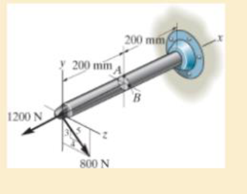
Solve Prob.8–68 for point B.
Expert Solution & Answer

Trending nowThis is a popular solution!

Students have asked these similar questions
A 10-kg box is pulled along P,Na rough surface by a force P, as shown in thefigure. The pulling force linearly increaseswith time, while the particle is motionless att = 0s untilit reaches a maximum force of100 Nattimet = 4s. If the ground has staticand kinetic friction coefficients of u, = 0.6 andHU, = 0.4 respectively, determine the velocityof the
A
1
0
-
kg box is pulled along P
,
N
a rough surface by a force P
,
as shown in the
figure. The pulling force linearly increases
with time, while the particle is motionless at
t
=
0
s untilit reaches a maximum force of
1
0
0
Nattimet
=
4
s
.
If the ground has static
and kinetic friction coefficients of u
,
=
0
.
6
and
HU
,
=
0
.
4
respectively, determine the velocity
of the particle att
=
4
s
.
Calculate the speed of the driven member with the following conditions:
Diameter of the motor pulley: 4 in Diameter of the driven pulley: 12 in Speed of the motor pulley: 1800 rpm
4. In the figure, shaft A made of AISI 1010 hot-rolled steel, is welded to a fixed
support and is subjected to loading by equal and opposite Forces F via shaft B.
Stress concentration factors K₁ (1.7) and Kts (1.6) are induced by the 3mm fillet.
Notch sensitivities are q₁=0.9 and qts=1. The length of shaft A from the fixed
support to the connection at shaft B is 1m. The load F cycles from 0.5 to 2kN and
a static load P is 100N. For shaft A, find the factor of safety (for infinite life) using
the modified Goodman fatigue failure criterion.
3 mm
fillet
Shaft A
20 mm
25 mm
Shaft B
25 mm
Chapter 8 Solutions
MECHANICS OF MATERIALS (LOOSE)-W/ACCESS
Ch. 8.1 - If it is subjected to an internal pressure of p =...Ch. 8.1 - If it is subjected to an internal pressure of p =...Ch. 8.1 - The thin-walled cylinder can be supported in one...Ch. 8.1 - If the inner diameter of the tank is 22 in., and...Ch. 8.1 - Air pressure in the cylinder is increased by...Ch. 8.1 - Determine the maximum force P that can be exerted...Ch. 8.1 - A boiler is constructed of 8-mm-thick steel plates...Ch. 8.1 - 88. The steel water pipe has an inner diameter of...Ch. 8.1 - The steel water pipe has an inner diameter of 12...Ch. 8.1 - The A-36-steel band is 2 in. wide and is secured...
Ch. 8.1 - The gas pipe line is supported every 20 ft by...Ch. 8.1 - A pressure-vessel head is fabricated by welding...Ch. 8.1 - An A-36-steel hoop has an inner diameter of 23.99...Ch. 8.1 - The ring, having the dimensions shown, is placed...Ch. 8.1 - The inner ring A has an inner radius r1 and outer...Ch. 8.1 - Two hemispheres having an inner radius of 2 ft and...Ch. 8.1 - In order to increase the strength of the pressure...Ch. 8.2 - Show the results on the left segment.Ch. 8.2 - Show the stress that each of these loads produce...Ch. 8.2 - Fundamental Problems F81. Determine the normal...Ch. 8.2 - Show the results in a differential element at the...Ch. 8.2 - Determine the state of stress at point A on the...Ch. 8.2 - Determine the magnitude of the load P that will...Ch. 8.2 - Determine the state of stress at point B. Show the...Ch. 8.2 - Determine the state of stress at point A on the...Ch. 8.2 - Determine the state of stress at point A on the...Ch. 8.2 - Show the results in a differential element at the...Ch. 8.2 - Determine the shortest distance d to the edge of...Ch. 8.2 - The plate has a thickness of 20 mm and P acts...Ch. 8.2 - Plot the distribution of normal stress acting...Ch. 8.2 - Also, plot the normal-stress distribution over the...Ch. 8.2 - If the allowable normal stress for the steel is...Ch. 8.2 - If the applied force P = 1.50 kip, determine the...Ch. 8.2 - Determine the maximum normal stress on the cross...Ch. 8.2 - If the wood has an allowable normal stress of...Ch. 8.2 - Determine the maximum normal stress along section...Ch. 8.2 - Sketch the stress distribution along section aa of...Ch. 8.2 - Sketch the normal-stress distribution acting over...Ch. 8.2 - Determine the state of stress at points A and B,...Ch. 8.2 - If the force of 100 N is applied to the handles,...Ch. 8.2 - Determine the stress components at point A on the...Ch. 8.2 - Determine the stress components at point B on the...Ch. 8.2 - Determine the normal stress developed at points A...Ch. 8.2 - Sketch the normal-stress distribution acting over...Ch. 8.2 - Determine the state of stress at points A and B,...Ch. 8.2 - Determine the state of stress at point A on the...Ch. 8.2 - Determine the state of stress at point B on the...Ch. 8.2 - Determine the state of stress acting at point D....Ch. 8.2 - Determine the state of stress acting at point E....Ch. 8.2 - If it is subjected to the force system shown,...Ch. 8.2 - Solve Prob.840 for point B.Ch. 8.2 - Determine the stress components acting on the...Ch. 8.2 - Determine the stress components acting on the...Ch. 8.2 - Neglect the weight of the block.Ch. 8.2 - Neglect the weight of the block.Ch. 8.2 - He is supported uniformly by two bars, each having...Ch. 8.2 - Determine the state of stress at point A, and show...Ch. 8.2 - Determine the state of stress at point B, and show...Ch. 8.2 - Determine the state of stress at point C, and show...Ch. 8.2 - Determine the maximum radius e at which the load P...Ch. 8.2 - Specify the region to which this load can be...Ch. 8.2 - Determine the smallest force P that can be applied...Ch. 8.2 - The coiled spring is subjected to a force P. If we...Ch. 8.2 - The pins at C and D are at the same location as...Ch. 8.2 - Determine the state of stress at point A, and show...Ch. 8.2 - Determine the state of stress at point B, and show...Ch. 8.2 - Determine the stress components at points A and B...Ch. 8.2 - Determine the stress components at points C and D...Ch. 8.2 - Determine the stress components in the support...Ch. 8.2 - Determine the stress components in the support...Ch. 8.2 - If the force at the ram on the clamp at D is P= 8...Ch. 8.2 - Determine the maximum ram force P that can be...Ch. 8.2 - and an outer radius of 3.00 in. If the face of the...Ch. 8.2 - for points E and F.Ch. 8.2 - Determine the stress components at points A and B...Ch. 8.2 - Solve Prob.8-65 for points C and D.Ch. 8.2 - Due to internal gearing, this causes the block to...Ch. 8.2 - Determine the state of stress at point A and show...Ch. 8.2 - Solve Prob.868 for point B.Ch. 8.2 - Determine the stress components at point A. Sketch...Ch. 8.2 - for the stress components at point B.Ch. 8.2 - Determine the state of stress at point A at...Ch. 8.2 - Determine the state of stress at point B at...Ch. 8 - If it supports a cable loading of 800 lb,...Ch. 8 - Determine the state of stress at point E on the...Ch. 8 - Determine the state of stress at point F on the...Ch. 8 - The suspender arm AE has a square cross-sectional...Ch. 8 - If the cross section of the femur at section aa...Ch. 8 - If it has a mass of 5 kg/m, determine the largest...Ch. 8 - and is used to support the vertical reactions of...Ch. 8 - and is used to support the vertical reactions of...
Knowledge Booster


Learn more about
Need a deep-dive on the concept behind this application? Look no further. Learn more about this topic, mechanical-engineering and related others by exploring similar questions and additional content below.Similar questions
- Please sovle this for me and please don't use aiarrow_forwardPlease sovle this for me and please don't use aiarrow_forward3. The cold-drawn AISI 1040 steel bar shown in the figure is subjected to a completely reversed axial load fluctuating between 28 kN in compression to 28 kN in tension. Estimate the fatigue factor of safety based on achieving infinite life (using Goodman line) and the yielding factor of safety. If infinite life is not predicted, estimate the number of cycles to failure. 25 mm + 6-mm D. 10 mmarrow_forward
- CORRECT AND DETAILED SOLUTION WITH FBD ONLY. I WILL UPVOTE 1. The truss shown is supported by hinge at A and cable at E.Given: H = 4m, S = 1.5 m, α = 75⁰, θ = 33⁰.Allowable tensile stress in cable = 64 MPa.Allowable compressive stress in all members = 120 MPaAllowable tensile stress in all members = 180 MPa1.Calculate the maximum permissible P, in kN, if the diameter of the cable is 20 mm.2.If P = 40 kN, calculate the required area (mm2) of member BC.3. If members have solid square section, with dimension 15 mm, calculate the maximum permissible P (kN) based on the allowable strength of member HI.ANSWERS: (1) 45.6 kN; (2) 83.71 mm2; (3) 171.76 kNarrow_forwardCORRECT AND DETAILED SOLUTION WITH FBD ONLY. I WILL UPVOTE 2: A wire 4 meters long is stretched horizontally between points 4 meters apart. The wire is 25 mm2 in cross-section with a modulus of elasticity of 200 GPa. A load W placed at the center of the wire produces a sag Δ.1.Calculate the tension (N) in the wire if sag Δ = 30 mm.2.Calculate the magnitude of W, in N, if sag Δ = 54.3 mm.3. If W is 60 N, what is the sag (in mm)?ANSWERS: (1) 562 N, (2) 100 N, (3) 45.8 Narrow_forwardCORRECT AND DETAILED SOLUTION WITH FBD ONLY. I WILL UPVOTE 4 : A cable and pulley system at D is used to bring a 230-kg pole (ACB) to a vertical position as shown. The cable has tensile force T and is attached at C. The length of the pole is 6.0 m, the outer diameter is d = 140 mm, and the wall thickness t = 12 mm. The pole pivots about a pin at A. The allowable shear stress in the pin is 60 MPa and the allowable bearing stress is 90 MPa. The diameter of the cable is 8 mm.1.Find the minimum diameter (mm) of the pin at A to support the weight of the pole in the position shown.2.Calculate the elongation (mm) of the cable CD.3.Calculate the vertical displacement of point C, in mm.ANSWERS: (1) 6 mm, (2) 1.186 mm, (3) 1.337 mm--arrow_forward
- 1. Derive an expression for H(w) filter or bandpass/reject filter. = for the circuit below. Qualitatively determine if it's a high/lowpass L ell R ww Voarrow_forward2. Obtain the transfer function, H(w) = 0 for the circuit below for R₁ = 1 kQ2, R2 = 10 kQ, and Vi C = 1 μF. What role, if any, does the capacitor play? Explain. R₁ R2 + C + Voarrow_forwardCORRECT AND DETAILED SOLUTION WITH FBD ONLY. I WILL UPVOTE 3 (15 points): A 12-meter-long precast pile segment is to be lifted from a trailer down to the ground and then set in place prior to driving by a crane.1. If two slings are to be used in lifting the pile to the ground, at what distance from the ends must the slings be placed for minimum bending due to its own weight?2. At what distance from the ends must the slings be placed for minimum shear due to its own weight?3. Using one sling to set the pile in a vertical position before driving at what distance from one end must the sling be placed for minimum bending due to its own weight?ANSWERS: (1) 2.48 m, (2) 3.00 m, (3) 3.51 marrow_forward
arrow_back_ios
SEE MORE QUESTIONS
arrow_forward_ios
Recommended textbooks for you
 International Edition---engineering Mechanics: St...Mechanical EngineeringISBN:9781305501607Author:Andrew Pytel And Jaan KiusalaasPublisher:CENGAGE L
 Mechanics of Materials (MindTap Course List)Mechanical EngineeringISBN:9781337093347Author:Barry J. Goodno, James M. GerePublisher:Cengage Learning
International Edition---engineering Mechanics: St...
Mechanical Engineering
ISBN:9781305501607
Author:Andrew Pytel And Jaan Kiusalaas
Publisher:CENGAGE L
Mechanics of Materials (MindTap Course List)
Mechanical Engineering
ISBN:9781337093347
Author:Barry J. Goodno, James M. Gere
Publisher:Cengage Learning
Solids: Lesson 53 - Slope and Deflection of Beams Intro; Author: Jeff Hanson;https://www.youtube.com/watch?v=I7lTq68JRmY;License: Standard YouTube License, CC-BY