
Videos
8-33 to 8-36 The figure illustrates the non-permanent connection of a steel cylinder head to a grade 30 cast- iron pressure vessel using N bolts. A confined gasket seal has an effective sealing diameter D. The cylinder stores gas at a maximum pressure pg. For the specifications given in the table for the specific problem assigned, select a suitable bolt length from the preferred sizes in Table A-17, then determine the yielding factor of safety np, the load factor nL, and the joint separation factor n0.
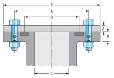
| Problem Number | 8-33 | 8-34 | 8-35 | 8-36 |
| A | 20 mm |
|
20 mm |
|
| B | 20 mm |
|
25 mm |
|
| C | 100 mm | 3.5 in | 0.8 m | 3.25 in |
| D | 150 mm | 4.25 in | 0.9 m | 3.5 in |
| E | 200 mm | 6 in | 1.0 m | 5.5 in |
| F | 300 mm | 8 in | 1.1 m | 7 in |
| N | 10 | 10 | 36 | 8 |
| pg | 6 MPa | 1500 psi | 550 kPa | 1200 psi |
| Bolt grade | ISO 9.8 | SAE 5 | ISO 10.9 | SAE 8 |
| Bolt spec. | M12 × 1.75 |
|
M10 × 1.5 |
|
The yield factor of safety.
The load factor of safety.
The joint separation factor.
Answer to Problem 36P
The yield factor of safety is
The load factor of safety is
The joint separation factor is
Explanation of Solution
Write the expression of the length of the material squeeze between the bolt face and washer face.
Here the length of the material squeeze between the bolt face and washer face is
Write the expression for the length of the bolt.
Here the length of bolt is
Write the expression of the threaded length for hexagonal bolt.
Here the threaded length is
Write the expression of the length of the unthreaded portion in grip.
Here, the length of the unthreaded portion in the grip is
Write the expression of the length of the threaded portion in grip.
Here, the length of threaded portion in the grip is
Write the expression of the major area diameter.
Here the nominal diameter of the bolt is
Write the expression of the stiffness for the bolt.
Here the bolt stiffness is
Write the expression of stiffness for the steel cylinder.
Here the stiffness of the steel cylinder is
Write the expression for the midpoint of the complete joint.
Here, the midpoint of the joint is
Write the expression of the thickness of the upper frustum.
Here, the thickness of upper frustum of the gasket is
Write the expression for the effective sealing diameter of the gasket sealing in upper frustum.
Here, the effective sealing diameter of upper frustum of the gasket sealing is
Write the expression for the stiffness of the upper frustum of cast iron vessel.
Here, the stiffness of the cast-iron pressure vessel in the upper frustum is
Write the expression for the stiffness of the lower frustum of the cast iron vessel.
Here, the stiffness of the cast-iron pressure vessel in the lower frustum is
Write the expression for the stiffness of the member or assembly.
Here, the stiffness of the member is
Write the expression of joint constant.
Here the joint constant is
Write the expression of initial tension in the bolt.
Here the tensile stress area is
Write the expression of the effective area of the cylinder.
Here, the effective area of the cylinder is
Write the expression for the total force acting on the assembly.
Here, the total load acting on the assembly is
Write the expression for the load acting on each bolt.
Here, the number of bolt is
Write the expression for yield factor of safety.
Here the overload factor of safety is
Write the expression of overload factor of safety.
Here the overload factor of safety is
Write the expression of joint separation factor of safety.
Here the factor of safety based on joint separation is
Conclusion:
Substitute
Refer to Table
Substitute
Substitute
Substitute
Substitute
Substitute
Refer to Table
Refer to Table
Substitute
Substitute
Substitute
Substitute
Substitute
Refer to Table
Substitute
Substitute
Substitute
Substitute
Refer to Table
Substitute
Substitute
Substitute
Substitute
Substitute
Thus, the yield factor of safety is
Substitute
Thus, the load factor of safety is
Substitute
Thus, the joint separation factor is
Want to see more full solutions like this?
Chapter 8 Solutions
Shigley's Mechanical Engineering Design (McGraw-Hill Series in Mechanical Engineering)


- The state of stress at a point is σ = -4.00 kpsi, σy = 16.00 kpsi, σ = -14.00 kpsi, Try = 11.00 kpsi, Tyz = 8.000 kpsi, and T = -14.00 kpsi. Determine the principal stresses. The principal normal stress σ₁ is determined to be [ The principal normal stress σ2 is determined to be [ The principal normal stress σ3 is determined to be kpsi. kpsi. The principal shear stress 71/2 is determined to be [ The principal shear stress 7½ is determined to be [ The principal shear stress T₁/, is determined to be [ kpsi. kpsi. kpsi. kpsi.arrow_forwardRepeat Problem 28, except using a shaft that is rotatingand transmitting a torque of 150 N * m from the left bearing to the middle of the shaft. Also, there is a profile keyseat at the middle under the load. (I want to understand this problem)arrow_forwardProb 2. The material distorts into the dashed position shown. Determine the average normal strains &x, Ey and the shear strain Yxy at A, and the average normal strain along line BE. 50 mm B 200 mm 15 mm 30 mm D ΕΙ 50 mm x A 150 mm Farrow_forward
- Prob 3. The triangular plate is fixed at its base, and its apex A is given a horizontal displacement of 5 mm. Determine the shear strain, Yxy, at A. Prob 4. The triangular plate is fixed at its base, and its apex A is given a horizontal displacement of 5 mm. Determine the average normal strain & along the x axis. Prob 5. The triangular plate is fixed at its base, and its apex A is given a horizontal displacement of 5 mm. Determine the average normal strain &x along the x' axis. x' 45° 800 mm 45° 45% 800 mm 5 mmarrow_forwardAn airplane lands on the straight runaway, originally travelling at 110 ft/s when s = 0. If it is subjected to the decelerations shown, determine the time t' needed to stop the plane and construct the s -t graph for the motion. draw a graph and show all work step by steparrow_forwarddny dn-1y dn-1u dn-24 +a1 + + Any = bi +b₂- + +bnu. dtn dtn-1 dtn-1 dtn-2 a) Let be a root of the characteristic equation 1 sn+a1sn- + +an = : 0. Show that if u(t) = 0, the differential equation has the solution y(t) = e\t. b) Let к be a zero of the polynomial b(s) = b₁s-1+b2sn−2+ Show that if the input is u(t) equation that is identically zero. = .. +bn. ekt, then there is a solution to the differentialarrow_forward
- B 60 ft WAB AB 30% : The crane's telescopic boom rotates with the angular velocity w = 0.06 rad/s and angular acceleration a = 0.07 rad/s². At the same instant, the boom is extending with a constant speed of 0.8 ft/s, measured relative to the boom. Determine the magnitude of the acceleration of point B at this instant.arrow_forwardThe motion of peg P is constrained by the lemniscate curved slot in OB and by the slotted arm OA. (Figure 1) If OA rotates counterclockwise with a constant angular velocity of 0 = 3 rad/s, determine the magnitude of the velocity of peg P at 0 = 30°. Express your answer to three significant figures and include the appropriate units. Determine the magnitude of the acceleration of peg P at 0 = 30°. Express your answer to three significant figures and include the appropriate units. 0 (4 cos 2 0)m² B Aarrow_forward5: The structure shown was designed to support a30-kN load. It consists of a boom AB with a 30 x 50-mmrectangular cross section and a rod BC with a 20-mm-diametercircular cross section. The boom and the rod are connected bya pin at B and are supported by pins and brackets at A and C,respectively.1. Calculate the normal stress in boom AB and rod BC,indicate if in tension or compression.2. Calculate the shear stress of pins at A, B and C.3. Calculate the bearing stresses at A in member AB,and in the bracket.arrow_forward
- 4: The boom AC is a 4-in. square steel tube with a wallthickness of 0.25 in. The boom is supported by the 0.5-in.-diameter pinat A, and the 0.375-in.-diameter cable BC. The working stresses are 25ksi for the cable, 18 ksi for the boom, and 13.6 ksi for shear in the pin.Neglect the weight of the boom.1. Calculate the maximum value of P (kips) based on boom compression and the maximum value of P (kips) based on tension in the cable.2. Calculate the maximum value of P (kips) based on shear in pin.arrow_forward3: A steel strut S serving as a brace for a boat hoist transmits a compressive force P = 54 kN to the deck of a pier as shown in Fig. STR-08. The strut has a hollow square cross section with a wall thickness t =12mm and the angle θ between the strut and the horizontal is 40°. A pin through the strut transmits the compressive force from the strut to two gusset plates G that are welded to the base plate B. Four anchor bolts fasten the base plate to the deck. The diameter of the pin is 20mm, the thickness of the gusset plates is 16mm, the thickness of the base plate is 8mm, and the diameter of the anchor bolts is 12mm. Disregard any friction between the base plate and the deck.1. Determine the shear stress in the pin, in MPa and the shear stress in the anchor bolts, in MPa.2. Determine the bearing stress in the strut holes, in MPa.arrow_forward1. In the figure, the beam, W410x67, with 9 mm web thicknesssubjects the girder, W530x109 with 12 mm web thickness to a shear load,P (kN). 2L – 90 mm × 90 mm × 6 mm with bolts frame the beam to thegirder.Given: S1 = S2 = S5 = 40 mm; S3 = 75 mm; S4 = 110 mmAllowable Stresses are as follows:Bolt shear stress, Fv = 125 MPaBolt bearing stress, Fp = 510 MPa1. Determine the allowable load, P (kN), based on the shearcapacity of the 4 – 25 mm diameter bolts (4 – d1) and calculate the allowable load, P (kN), based on bolt bearing stress on the web of the beam.2. If P = 450 kN, determine the minimum diameter (mm) of 4 – d1based on allowable bolt shear stress and bearing stress of thebeam web.arrow_forward
 Mechanics of Materials (MindTap Course List)Mechanical EngineeringISBN:9781337093347Author:Barry J. Goodno, James M. GerePublisher:Cengage Learning