
Mechanics of Materials, 7th Edition
7th Edition
ISBN: 9780073398235
Author: Ferdinand P. Beer, E. Russell Johnston Jr., John T. DeWolf, David F. Mazurek
Publisher: McGraw-Hill Education
expand_more
expand_more
format_list_bulleted
Videos
Textbook Question
Chapter 7.9, Problem 128P
7.128 through 7.131 For the given state of plane strain, use the method of Sec. 7.7A to determine the state of plane strain associated, with axes x' and y' rotated through the given angle
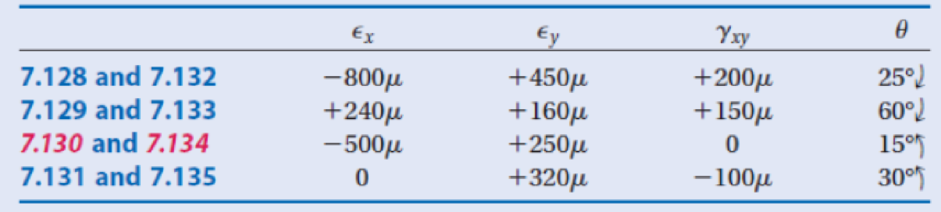
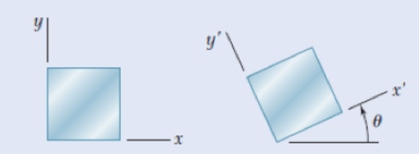
Fig. P7.128 through P7.135
Expert Solution & Answer
Want to see the full answer?
Check out a sample textbook solution
Students have asked these similar questions
PROBLEM 3.46
The solid cylindrical rod BC of length L = 600
mm is attached to the rigid lever AB of length a
= 380 mm and to the support at C. When a 500
N force P is applied at A, design specifications
require that the displacement of A not exceed
25 mm when a 500 N force P is applied at A
For the material indicated determine the
required diameter of the rod.
Aluminium: Tall = 65 MPa, G = 27 GPa.
A
Find the equivalent mass of the rocker arm assembly with respect to the x coordinate.
k₁
mi
m2
k₁
2. Figure below shows a U-tube manometer open at both ends and containing a column of liquid
mercury of length l and specific weight y. Considering a small displacement x of the manometer
meniscus from its equilibrium position (or datum), determine the equivalent spring constant associated
with the restoring force.
Datum
Area, A
Chapter 7 Solutions
Mechanics of Materials, 7th Edition
Ch. 7.1 - 7.1 through 7.4 For the given state of stress,...Ch. 7.1 - 7.1 through 7.4 For the given state of stress,...Ch. 7.1 - 7.1 through 7.4 For the given state of stress,...Ch. 7.1 - 7.1 through 7.4 For the given state of stress,...Ch. 7.1 - 7.5 through 7.8 For the given state of stress,...Ch. 7.1 - 7.5 through 7.8 For the given state of stress,...Ch. 7.1 - 7.5 through 7.8 For the given state of stress,...Ch. 7.1 - 7.5 through 7.8 For the given state of stress,...Ch. 7.1 - 7.9 through 7.12 For the given state of stress,...Ch. 7.1 - 7.9 through 7.12 For the given state of stress,...
Ch. 7.1 - 7.9 through 7.12 For the given state of stress,...Ch. 7.1 - 7.9 through 7.12 For the given state of stress,...Ch. 7.1 - 7.13 through 7.16 For the given state of stress,...Ch. 7.1 - 7.13 through 7.16 For the given state of stress,...Ch. 7.1 - 7.13 through 7.16 For the given state of stress,...Ch. 7.1 - 7.13 through 7.16 For the given state of stress,...Ch. 7.1 - 7.17 and 7.18 The grain of a wooden member forms...Ch. 7.1 - 7.17 and 7.18 The grain of a wooden member forms...Ch. 7.1 - Two wooden members of 80 120-mm uniform...Ch. 7.1 - Two wooden members of 80 120-mm uniform...Ch. 7.1 - The centric force P is applied to a short post as...Ch. 7.1 - Two members of uniform cross section 50 80 mm are...Ch. 7.1 - The axle of an automobile is acted upon by the...Ch. 7.1 - A 400-lb vertical force is applied at D to a gear...Ch. 7.1 - A mechanic uses a crowfoot wrench to loosen a bolt...Ch. 7.1 - The steel pipe AB has a 102-mm outer diameter and...Ch. 7.1 - For the state of plane stress shown, determine the...Ch. 7.1 - For the state of plane stress shown, determine (a)...Ch. 7.1 - For the state of plane stress shown, determine (a)...Ch. 7.1 - Determine the range of values of x for which the...Ch. 7.2 - Solve Probs. 7.5 and 7.9, using Mohr's circle. 7.5...Ch. 7.2 - Solve Probs. 7.7 and 7.11, using Mohrs circle. 7.5...Ch. 7.2 - Solve Prob. 7.10, using Mohrs circle. 7.9 through...Ch. 7.2 - Solve Prob. 7.12, using Mohr's circle. 7.9 through...Ch. 7.2 - Solve Prob. 7.13, using Mohr's circle. 7.13...Ch. 7.2 - Solve Prob. 7.14, using Mohr's circle. 7.13...Ch. 7.2 - Solve Prob. 7.15, using Mohr's circle. 7.13...Ch. 7.2 - Solve Prob. 7.16, using Mohr's circle. 7.13...Ch. 7.2 - Solve Prob. 7.17, using Mohr's circle. 7.17 and...Ch. 7.2 - Solve Prob. 7.18, using Mohr's circle. 7.17 and...Ch. 7.2 - Solve Prob. 7.19, using Mohr's circle. 7.19 Two...Ch. 7.2 - Solve Prob. 7.20, using Mohr's circle. 7.20 Two...Ch. 7.2 - Solve Prob. 7.21, using Mohrs circle. 7.21 The...Ch. 7.2 - Solve Prob. 7.22, using Mohrs circle. 7.22 Two...Ch. 7.2 - Solve Prob. 7.23, using Mohr's circle. 7.23 The...Ch. 7.2 - Solve Prob. 7.24, using Mohr's circle 7.24 A...Ch. 7.2 - Solve Prob. 7.25, using Mohrs circle. 7.25 A...Ch. 7.2 - Solve Prob. 7.26, using Mohrs circle. 7.26 The...Ch. 7.2 - Solve Prob. 7.27, using Mohr's circle. 7.27 For...Ch. 7.2 - Solve Prob. 7.28, using Mohrs circle. 7.28 For the...Ch. 7.2 - Solve Prob. 7.29, using Mohr's circle. 7.29 For...Ch. 7.2 - Solve Prob. 7.30, using Mohrs circle. 7.30...Ch. 7.2 - Solve Prob. 7.29, using Mohr's circle and assuming...Ch. 7.2 - 7.54 and 7.55 Determine the principal planes and...Ch. 7.2 - 7.54 and 7.55 Determine the principal planes and...Ch. 7.2 - 7.56 and 7.57 Determine the principal planes and...Ch. 7.2 - 7.56 and 7.57 Determine the principal planes and...Ch. 7.2 - For the element shown, determine the range of...Ch. 7.2 - For the element shown, determine the range of...Ch. 7.2 - For the state of stress shown, determine the range...Ch. 7.2 - For the state of stress shown, determine the range...Ch. 7.2 - For the state of stress shown, determine the range...Ch. 7.2 - For the state of stress shown, it is known that...Ch. 7.2 - The Mohr's circle shown corresponds to the state...Ch. 7.2 - (a) Prove that the expression xy 2xywhere x,...Ch. 7.5 - For the state of plane stress shown, determine the...Ch. 7.5 - For the state of plane stress shown, determine the...Ch. 7.5 - For the state of stress shown, determine the...Ch. 7.5 - For the state of stress shown, determine the...Ch. 7.5 - 7.70 and 7.71 For the state of stress shown,...Ch. 7.5 - 7.70 and 7.71 For the state of stress shown,...Ch. 7.5 - 7.72 and 7.73 For the state of stress shown,...Ch. 7.5 - 7.72 and 7.73 For the state of stress shown,...Ch. 7.5 - For the state of stress shown, determine the value...Ch. 7.5 - For the state of stress shown, determine the value...Ch. 7.5 - Prob. 76PCh. 7.5 - For the state of stress shown, determine two...Ch. 7.5 - For the state of stress shown, determine the range...Ch. 7.5 - Prob. 79PCh. 7.5 - Prob. 80PCh. 7.5 - The state of plane stress shown occurs in a...Ch. 7.5 - Prob. 82PCh. 7.5 - The state of plane stress shown occurs in a...Ch. 7.5 - Solve Prob. 7.83, using the...Ch. 7.5 - The 38-mm-diameter shaft AB is made of a grade of...Ch. 7.5 - Solve Prob. 7.85, using the...Ch. 7.5 - The 1.5-in.-diameter shaft AB is made of a grade...Ch. 7.5 - Prob. 88PCh. 7.5 - Prob. 89PCh. 7.5 - Prob. 90PCh. 7.5 - Prob. 91PCh. 7.5 - Prob. 92PCh. 7.5 - Prob. 93PCh. 7.5 - Prob. 94PCh. 7.5 - Prob. 95PCh. 7.5 - Prob. 96PCh. 7.5 - Prob. 97PCh. 7.6 - A spherical pressure vessel has an outer diameter...Ch. 7.6 - A spherical gas container having an inner diameter...Ch. 7.6 - The maximum gage pressure is known to be 1150 psi...Ch. 7.6 - Prob. 101PCh. 7.6 - Prob. 102PCh. 7.6 - A basketball has a 300-mm outer diameter and a...Ch. 7.6 - The unpressurized cylindrical storage tank shown...Ch. 7.6 - Prob. 105PCh. 7.6 - Prob. 106PCh. 7.6 - Prob. 107PCh. 7.6 - Prob. 108PCh. 7.6 - Prob. 109PCh. 7.6 - Prob. 110PCh. 7.6 - Prob. 111PCh. 7.6 - The cylindrical portion of the compressed-air tank...Ch. 7.6 - Prob. 113PCh. 7.6 - Prob. 114PCh. 7.6 - Prob. 115PCh. 7.6 - Square plates, each of 0.5-in. thickness, can be...Ch. 7.6 - The pressure tank shown has a 0.375-in. wall...Ch. 7.6 - Prob. 118PCh. 7.6 - Prob. 119PCh. 7.6 - A pressure vessel of 10-in. inner diameter and...Ch. 7.6 - Prob. 121PCh. 7.6 - A torque of magnitude T = 12 kN-m is applied to...Ch. 7.6 - The tank shown has a 180-mm inner diameter and a...Ch. 7.6 - The compressed-air tank AB has a 250-rnm outside...Ch. 7.6 - In Prob. 7.124, determine the maximum normal...Ch. 7.6 - Prob. 126PCh. 7.6 - Prob. 127PCh. 7.9 - 7.128 through 7.131 For the given state of plane...Ch. 7.9 - 7.128 through 7.131 For the given state of plane...Ch. 7.9 - Prob. 130PCh. 7.9 - 7.128 through 7.131 For the given state of plane...Ch. 7.9 - Prob. 132PCh. 7.9 - Prob. 133PCh. 7.9 - Prob. 134PCh. 7.9 - 7.128 through 7.131 For the given state of plane...Ch. 7.9 - 7.136 through 7.139 The following state of strain...Ch. 7.9 - Prob. 137PCh. 7.9 - Prob. 138PCh. 7.9 - Prob. 139PCh. 7.9 - Prob. 140PCh. 7.9 - 7.140 through 7.143 For the given state of plane...Ch. 7.9 - Prob. 142PCh. 7.9 - Prob. 143PCh. 7.9 - Prob. 144PCh. 7.9 - The strains determined by the use of the rosette...Ch. 7.9 - Prob. 146PCh. 7.9 - Prob. 147PCh. 7.9 - Show that the sum of the three strain measurements...Ch. 7.9 - Prob. 149PCh. 7.9 - Prob. 150PCh. 7.9 - Solve Prob. 7.150, assuming that the rosette at...Ch. 7.9 - Prob. 152PCh. 7.9 - Prob. 153PCh. 7.9 - Prob. 154PCh. 7.9 - Prob. 155PCh. 7.9 - The given state of plane stress is known to exist...Ch. 7.9 - The following state of strain has been determined...Ch. 7 - A steel pipe of 12-in. outer diameter is...Ch. 7 - Two steel plates of uniform cross section 10 80...Ch. 7 - Prob. 160RPCh. 7 - Prob. 161RPCh. 7 - For the state of stress shown, determine the...Ch. 7 - For the state of stress shown, determine the value...Ch. 7 - The state of plane stress shown occurs in a...Ch. 7 - The compressed-air tank AB has an inner diameter...Ch. 7 - For the compressed-air tank and loading of Prob....Ch. 7 - Prob. 167RPCh. 7 - Prob. 168RPCh. 7 - Prob. 169RP
Knowledge Booster


Learn more about
Need a deep-dive on the concept behind this application? Look no further. Learn more about this topic, mechanical-engineering and related others by exploring similar questions and additional content below.Similar questions
- 1. The consequences of a head-on collision of two automobiles can be studied by considering the impact of the automobile on a barrier, as shown in figure below. Construct a mathematical model (i.e., draw the diagram) by considering the masses of the automobile body, engine, transmission, and suspension and the elasticity of the bumpers, radiator, sheet metal body, driveline, and engine mounts.arrow_forward3.) 15.40 – Collar B moves up at constant velocity vB = 1.5 m/s. Rod AB has length = 1.2 m. The incline is at angle = 25°. Compute an expression for the angular velocity of rod AB, ė and the velocity of end A of the rod (✓✓) as a function of v₂,1,0,0. Then compute numerical answers for ȧ & y_ with 0 = 50°.arrow_forward2.) 15.12 The assembly shown consists of the straight rod ABC which passes through and is welded to the grectangular plate DEFH. The assembly rotates about the axis AC with a constant angular velocity of 9 rad/s. Knowing that the motion when viewed from C is counterclockwise, determine the velocity and acceleration of corner F.arrow_forward
- 500 Q3: The attachment shown in Fig.3 is made of 1040 HR. The static force is 30 kN. Specify the weldment (give the pattern, electrode number, type of weld, length of weld, and leg size). Fig. 3 All dimension in mm 30 kN 100 (10 Marks)arrow_forward(read image) (answer given)arrow_forwardA cylinder and a disk are used as pulleys, as shown in the figure. Using the data given in the figure, if a body of mass m = 3 kg is released from rest after falling a height h 1.5 m, find: a) The velocity of the body. b) The angular velocity of the disk. c) The number of revolutions the cylinder has made. T₁ F Rd = 0.2 m md = 2 kg T T₂1 Rc = 0.4 m mc = 5 kg ☐ m = 3 kgarrow_forward
- (read image) (answer given)arrow_forward11-5. Compute all the dimensional changes for the steel bar when subjected to the loads shown. The proportional limit of the steel is 230 MPa. 265 kN 100 mm 600 kN 25 mm thickness X Z 600 kN 450 mm E=207×103 MPa; μ= 0.25 265 kNarrow_forwardT₁ F Rd = 0.2 m md = 2 kg T₂ Tz1 Rc = 0.4 m mc = 5 kg m = 3 kgarrow_forward
- 2. Find a basis of solutions by the Frobenius method. Try to identify the series as expansions of known functions. (x + 2)²y" + (x + 2)y' - y = 0 ; Hint: Let: z = x+2arrow_forward1. Find a power series solution in powers of x. y" - y' + x²y = 0arrow_forward3. Find a basis of solutions by the Frobenius method. Try to identify the series as expansions of known functions. 8x2y" +10xy' + (x 1)y = 0 -arrow_forward
arrow_back_ios
SEE MORE QUESTIONS
arrow_forward_ios
Recommended textbooks for you
 Elements Of ElectromagneticsMechanical EngineeringISBN:9780190698614Author:Sadiku, Matthew N. O.Publisher:Oxford University Press
 Mechanics of Materials (10th Edition)Mechanical EngineeringISBN:9780134319650Author:Russell C. HibbelerPublisher:PEARSON
 Thermodynamics: An Engineering ApproachMechanical EngineeringISBN:9781259822674Author:Yunus A. Cengel Dr., Michael A. BolesPublisher:McGraw-Hill Education
 Control Systems EngineeringMechanical EngineeringISBN:9781118170519Author:Norman S. NisePublisher:WILEY
 Mechanics of Materials (MindTap Course List)Mechanical EngineeringISBN:9781337093347Author:Barry J. Goodno, James M. GerePublisher:Cengage Learning
 Engineering Mechanics: StaticsMechanical EngineeringISBN:9781118807330Author:James L. Meriam, L. G. Kraige, J. N. BoltonPublisher:WILEY
Elements Of Electromagnetics
Mechanical Engineering
ISBN:9780190698614
Author:Sadiku, Matthew N. O.
Publisher:Oxford University Press
Mechanics of Materials (10th Edition)
Mechanical Engineering
ISBN:9780134319650
Author:Russell C. Hibbeler
Publisher:PEARSON
Thermodynamics: An Engineering Approach
Mechanical Engineering
ISBN:9781259822674
Author:Yunus A. Cengel Dr., Michael A. Boles
Publisher:McGraw-Hill Education
Control Systems Engineering
Mechanical Engineering
ISBN:9781118170519
Author:Norman S. Nise
Publisher:WILEY
Mechanics of Materials (MindTap Course List)
Mechanical Engineering
ISBN:9781337093347
Author:Barry J. Goodno, James M. Gere
Publisher:Cengage Learning
Engineering Mechanics: Statics
Mechanical Engineering
ISBN:9781118807330
Author:James L. Meriam, L. G. Kraige, J. N. Bolton
Publisher:WILEY
An Introduction to Stress and Strain; Author: The Efficient Engineer;https://www.youtube.com/watch?v=aQf6Q8t1FQE;License: Standard YouTube License, CC-BY