
Concept explainers
Videos
The compressed-air tank AB has a 250-rnm outside diameter and an 8-mm wall thickness. It is fitted with a collar by which a 40-kN force P is applied at B in the horizontal direction. Knowing that the gage pressure inside the tank is 5 MPa, determine the maximum normal stress and the maximum shearing stress at point K.
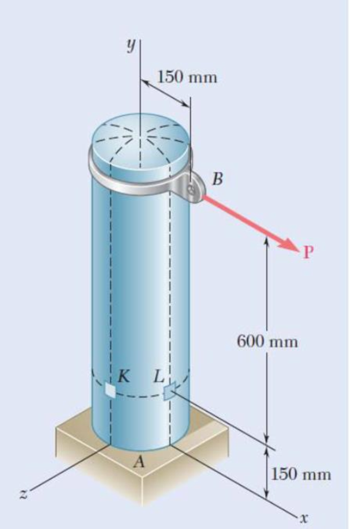
Fig. P7.124
Find the maximum normal stress and maximum shear stress at point K.
Answer to Problem 124P
The maximum normal stress and maximum shear stress at point K are
Explanation of Solution
Given information:
The outer diameter (d) of the tank is
The wall thickness (t) of the tank is
The magnitude of the load P is
The gage pressure (p) inside the tank is
Calculation:
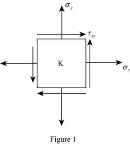
Consider an element at point K.
Show the stress acting on the point K as shown in Figure 1.
Calculate the inner radius of the vessel
Substitute
Show the expression for hoop stress acting on the tank as shown below.
Substitute
Show the expression for longitudinal stress acting on the vessel as shown below.
Substitute
Calculate the stress due to bending at point K as follows:
The point K lies in the neutral axis, then
The stress due to bending at point K,
Calculate the stress due to transverse shear as follows:
Consider the shear force acting on the tank is denoted by V. Then,
Consider the distance between the centre of the circular cross-section to the inner and outer surface of the wall are denoted by
Calculate the shear flow Q using the relation:
Substitute
Calculate the moment of inertia I of the cross-section using the relation:
Substitute
Calculate the shear stress using the relation:
Substitute
Show the total hoop stress
Calculate the radius of the Mohr circle using the relation:
Substitute
Show the expression for average stress acting on the vessel as shown below.
Substitute
Consider the principal stress are denoted by
Calculate the value of the
Substitute
Calculate the value of the
Substitute
The stress at point C is 0. Then,
Compare the value of stress
Get the maximum and minimum value of the stress as follows:
Thus, the maximum normal stress in the tank is
Calculate the maximum shear stress in the tank using the relation:
Substitute
Thus, the maximum shear stress in the tank is
Want to see more full solutions like this?
Chapter 7 Solutions
Mechanics of Materials, 7th Edition


- My ID#016948724 please solve this problems and show me every step clear to follow pleasearrow_forwardMy ID# 016948724arrow_forwardPlease do not use any AI tools to solve this question. I need a fully manual, step-by-step solution with clear explanations, as if it were done by a human tutor. No AI-generated responses, please.arrow_forward
- Please do not use any AI tools to solve this question. I need a fully manual, step-by-step solution with clear explanations, as if it were done by a human tutor. No AI-generated responses, please.arrow_forwardPlease do not use any AI tools to solve this question. I need a fully manual, step-by-step solution with clear explanations, as if it were done by a human tutor. No AI-generated responses, please.arrow_forward[Q2]: The cost information supplied by the cost accountant is as follows:Sales 20,00 units, $ 10 per unitCalculate the (a/ newsale guantity and (b) new selling price to earn the sameVariable cost $ 6 per unit, Fixed Cost $ 30,000, Profit $ 50,000profit ifi) Variable cost increases by $ 2 per unitil) Fixed cost increase by $ 10,000Ili) Variable cost increase by $ 1 per unit and fixed cost reduces by $ 10,000arrow_forward
- can you please help me perform Visual Inspection and Fractography of the attatched image: Preliminary examination to identify the fracture origin, suspected fatigue striation, and corrosion evidences.arrow_forwardcan you please help[ me conduct Causal Analysis (FTA) on the scenario attatched: FTA diagram which is a fault tree analysis diagram will be used to gain an overview of the entire path of failure from root cause to the top event (i.e., the swing’s detachment) and to identify interactions between misuse, material decay and inspection errors.arrow_forwardhi can you please help me in finding the stress intensity factor using a k-calcluator for the scenario attathced in the images.arrow_forward
 Elements Of ElectromagneticsMechanical EngineeringISBN:9780190698614Author:Sadiku, Matthew N. O.Publisher:Oxford University Press
 Mechanics of Materials (10th Edition)Mechanical EngineeringISBN:9780134319650Author:Russell C. HibbelerPublisher:PEARSON
 Thermodynamics: An Engineering ApproachMechanical EngineeringISBN:9781259822674Author:Yunus A. Cengel Dr., Michael A. BolesPublisher:McGraw-Hill Education
 Control Systems EngineeringMechanical EngineeringISBN:9781118170519Author:Norman S. NisePublisher:WILEY
 Mechanics of Materials (MindTap Course List)Mechanical EngineeringISBN:9781337093347Author:Barry J. Goodno, James M. GerePublisher:Cengage Learning
 Engineering Mechanics: StaticsMechanical EngineeringISBN:9781118807330Author:James L. Meriam, L. G. Kraige, J. N. BoltonPublisher:WILEY