
Mechanics of Materials, 7th Edition
7th Edition
ISBN: 9780073398235
Author: Ferdinand P. Beer, E. Russell Johnston Jr., John T. DeWolf, David F. Mazurek
Publisher: McGraw-Hill Education
expand_more
expand_more
format_list_bulleted
Concept explainers
Videos
Textbook Question
Chapter 7.2, Problem 35P
Solve Prob. 7.13, using Mohr's circle.
7.13 through 7.16 For the given state of stress, determine the normal and shearing stresses after the element shown has been rotated through (a) 25° clockwise, (b) 10° counterclockwise.
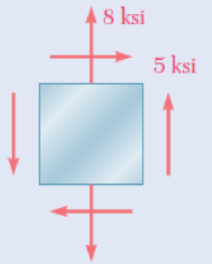
Fig. P7.13
Expert Solution & Answer
Want to see the full answer?
Check out a sample textbook solution
Students have asked these similar questions
(Read image) (Answer given)
Problem (17): water flowing in an open channel of a rectangular cross-section with width (b) transitions from a
mild slope to a steep slope (i.e., from subcritical to supercritical flow) with normal water depths of (y₁) and
(y2), respectively.
Given the values of y₁ [m], y₂ [m], and b [m], calculate the discharge in the channel (Q) in [Lit/s].
Givens:
y1 = 4.112 m
y2 =
0.387 m
b = 0.942 m
Answers:
( 1 ) 1880.186 lit/s
( 2 ) 4042.945 lit/s
( 3 ) 2553.11 lit/s
( 4 ) 3130.448 lit/s
Problem (14): A pump is being used to lift water from an underground
tank through a pipe of diameter (d) at discharge (Q). The total head
loss until the pump entrance can be calculated as (h₁ = K[V²/2g]), h
where (V) is the flow velocity in the pipe. The elevation difference
between the pump and tank surface is (h).
Given the values of h [cm], d [cm], and K [-], calculate the maximum
discharge Q [Lit/s] beyond which cavitation would take place at the
pump entrance. Assume Turbulent flow conditions.
Givens:
h = 120.31 cm
d = 14.455 cm
K = 8.976
Q
Answers:
(1) 94.917 lit/s
(2) 49.048 lit/s
( 3 ) 80.722 lit/s
68.588 lit/s
4
Chapter 7 Solutions
Mechanics of Materials, 7th Edition
Ch. 7.1 - 7.1 through 7.4 For the given state of stress,...Ch. 7.1 - 7.1 through 7.4 For the given state of stress,...Ch. 7.1 - 7.1 through 7.4 For the given state of stress,...Ch. 7.1 - 7.1 through 7.4 For the given state of stress,...Ch. 7.1 - 7.5 through 7.8 For the given state of stress,...Ch. 7.1 - 7.5 through 7.8 For the given state of stress,...Ch. 7.1 - 7.5 through 7.8 For the given state of stress,...Ch. 7.1 - 7.5 through 7.8 For the given state of stress,...Ch. 7.1 - 7.9 through 7.12 For the given state of stress,...Ch. 7.1 - 7.9 through 7.12 For the given state of stress,...
Ch. 7.1 - 7.9 through 7.12 For the given state of stress,...Ch. 7.1 - 7.9 through 7.12 For the given state of stress,...Ch. 7.1 - 7.13 through 7.16 For the given state of stress,...Ch. 7.1 - 7.13 through 7.16 For the given state of stress,...Ch. 7.1 - 7.13 through 7.16 For the given state of stress,...Ch. 7.1 - 7.13 through 7.16 For the given state of stress,...Ch. 7.1 - 7.17 and 7.18 The grain of a wooden member forms...Ch. 7.1 - 7.17 and 7.18 The grain of a wooden member forms...Ch. 7.1 - Two wooden members of 80 120-mm uniform...Ch. 7.1 - Two wooden members of 80 120-mm uniform...Ch. 7.1 - The centric force P is applied to a short post as...Ch. 7.1 - Two members of uniform cross section 50 80 mm are...Ch. 7.1 - The axle of an automobile is acted upon by the...Ch. 7.1 - A 400-lb vertical force is applied at D to a gear...Ch. 7.1 - A mechanic uses a crowfoot wrench to loosen a bolt...Ch. 7.1 - The steel pipe AB has a 102-mm outer diameter and...Ch. 7.1 - For the state of plane stress shown, determine the...Ch. 7.1 - For the state of plane stress shown, determine (a)...Ch. 7.1 - For the state of plane stress shown, determine (a)...Ch. 7.1 - Determine the range of values of x for which the...Ch. 7.2 - Solve Probs. 7.5 and 7.9, using Mohr's circle. 7.5...Ch. 7.2 - Solve Probs. 7.7 and 7.11, using Mohrs circle. 7.5...Ch. 7.2 - Solve Prob. 7.10, using Mohrs circle. 7.9 through...Ch. 7.2 - Solve Prob. 7.12, using Mohr's circle. 7.9 through...Ch. 7.2 - Solve Prob. 7.13, using Mohr's circle. 7.13...Ch. 7.2 - Solve Prob. 7.14, using Mohr's circle. 7.13...Ch. 7.2 - Solve Prob. 7.15, using Mohr's circle. 7.13...Ch. 7.2 - Solve Prob. 7.16, using Mohr's circle. 7.13...Ch. 7.2 - Solve Prob. 7.17, using Mohr's circle. 7.17 and...Ch. 7.2 - Solve Prob. 7.18, using Mohr's circle. 7.17 and...Ch. 7.2 - Solve Prob. 7.19, using Mohr's circle. 7.19 Two...Ch. 7.2 - Solve Prob. 7.20, using Mohr's circle. 7.20 Two...Ch. 7.2 - Solve Prob. 7.21, using Mohrs circle. 7.21 The...Ch. 7.2 - Solve Prob. 7.22, using Mohrs circle. 7.22 Two...Ch. 7.2 - Solve Prob. 7.23, using Mohr's circle. 7.23 The...Ch. 7.2 - Solve Prob. 7.24, using Mohr's circle 7.24 A...Ch. 7.2 - Solve Prob. 7.25, using Mohrs circle. 7.25 A...Ch. 7.2 - Solve Prob. 7.26, using Mohrs circle. 7.26 The...Ch. 7.2 - Solve Prob. 7.27, using Mohr's circle. 7.27 For...Ch. 7.2 - Solve Prob. 7.28, using Mohrs circle. 7.28 For the...Ch. 7.2 - Solve Prob. 7.29, using Mohr's circle. 7.29 For...Ch. 7.2 - Solve Prob. 7.30, using Mohrs circle. 7.30...Ch. 7.2 - Solve Prob. 7.29, using Mohr's circle and assuming...Ch. 7.2 - 7.54 and 7.55 Determine the principal planes and...Ch. 7.2 - 7.54 and 7.55 Determine the principal planes and...Ch. 7.2 - 7.56 and 7.57 Determine the principal planes and...Ch. 7.2 - 7.56 and 7.57 Determine the principal planes and...Ch. 7.2 - For the element shown, determine the range of...Ch. 7.2 - For the element shown, determine the range of...Ch. 7.2 - For the state of stress shown, determine the range...Ch. 7.2 - For the state of stress shown, determine the range...Ch. 7.2 - For the state of stress shown, determine the range...Ch. 7.2 - For the state of stress shown, it is known that...Ch. 7.2 - The Mohr's circle shown corresponds to the state...Ch. 7.2 - (a) Prove that the expression xy 2xywhere x,...Ch. 7.5 - For the state of plane stress shown, determine the...Ch. 7.5 - For the state of plane stress shown, determine the...Ch. 7.5 - For the state of stress shown, determine the...Ch. 7.5 - For the state of stress shown, determine the...Ch. 7.5 - 7.70 and 7.71 For the state of stress shown,...Ch. 7.5 - 7.70 and 7.71 For the state of stress shown,...Ch. 7.5 - 7.72 and 7.73 For the state of stress shown,...Ch. 7.5 - 7.72 and 7.73 For the state of stress shown,...Ch. 7.5 - For the state of stress shown, determine the value...Ch. 7.5 - For the state of stress shown, determine the value...Ch. 7.5 - Prob. 76PCh. 7.5 - For the state of stress shown, determine two...Ch. 7.5 - For the state of stress shown, determine the range...Ch. 7.5 - Prob. 79PCh. 7.5 - Prob. 80PCh. 7.5 - The state of plane stress shown occurs in a...Ch. 7.5 - Prob. 82PCh. 7.5 - The state of plane stress shown occurs in a...Ch. 7.5 - Solve Prob. 7.83, using the...Ch. 7.5 - The 38-mm-diameter shaft AB is made of a grade of...Ch. 7.5 - Solve Prob. 7.85, using the...Ch. 7.5 - The 1.5-in.-diameter shaft AB is made of a grade...Ch. 7.5 - Prob. 88PCh. 7.5 - Prob. 89PCh. 7.5 - Prob. 90PCh. 7.5 - Prob. 91PCh. 7.5 - Prob. 92PCh. 7.5 - Prob. 93PCh. 7.5 - Prob. 94PCh. 7.5 - Prob. 95PCh. 7.5 - Prob. 96PCh. 7.5 - Prob. 97PCh. 7.6 - A spherical pressure vessel has an outer diameter...Ch. 7.6 - A spherical gas container having an inner diameter...Ch. 7.6 - The maximum gage pressure is known to be 1150 psi...Ch. 7.6 - Prob. 101PCh. 7.6 - Prob. 102PCh. 7.6 - A basketball has a 300-mm outer diameter and a...Ch. 7.6 - The unpressurized cylindrical storage tank shown...Ch. 7.6 - Prob. 105PCh. 7.6 - Prob. 106PCh. 7.6 - Prob. 107PCh. 7.6 - Prob. 108PCh. 7.6 - Prob. 109PCh. 7.6 - Prob. 110PCh. 7.6 - Prob. 111PCh. 7.6 - The cylindrical portion of the compressed-air tank...Ch. 7.6 - Prob. 113PCh. 7.6 - Prob. 114PCh. 7.6 - Prob. 115PCh. 7.6 - Square plates, each of 0.5-in. thickness, can be...Ch. 7.6 - The pressure tank shown has a 0.375-in. wall...Ch. 7.6 - Prob. 118PCh. 7.6 - Prob. 119PCh. 7.6 - A pressure vessel of 10-in. inner diameter and...Ch. 7.6 - Prob. 121PCh. 7.6 - A torque of magnitude T = 12 kN-m is applied to...Ch. 7.6 - The tank shown has a 180-mm inner diameter and a...Ch. 7.6 - The compressed-air tank AB has a 250-rnm outside...Ch. 7.6 - In Prob. 7.124, determine the maximum normal...Ch. 7.6 - Prob. 126PCh. 7.6 - Prob. 127PCh. 7.9 - 7.128 through 7.131 For the given state of plane...Ch. 7.9 - 7.128 through 7.131 For the given state of plane...Ch. 7.9 - Prob. 130PCh. 7.9 - 7.128 through 7.131 For the given state of plane...Ch. 7.9 - Prob. 132PCh. 7.9 - Prob. 133PCh. 7.9 - Prob. 134PCh. 7.9 - 7.128 through 7.131 For the given state of plane...Ch. 7.9 - 7.136 through 7.139 The following state of strain...Ch. 7.9 - Prob. 137PCh. 7.9 - Prob. 138PCh. 7.9 - Prob. 139PCh. 7.9 - Prob. 140PCh. 7.9 - 7.140 through 7.143 For the given state of plane...Ch. 7.9 - Prob. 142PCh. 7.9 - Prob. 143PCh. 7.9 - Prob. 144PCh. 7.9 - The strains determined by the use of the rosette...Ch. 7.9 - Prob. 146PCh. 7.9 - Prob. 147PCh. 7.9 - Show that the sum of the three strain measurements...Ch. 7.9 - Prob. 149PCh. 7.9 - Prob. 150PCh. 7.9 - Solve Prob. 7.150, assuming that the rosette at...Ch. 7.9 - Prob. 152PCh. 7.9 - Prob. 153PCh. 7.9 - Prob. 154PCh. 7.9 - Prob. 155PCh. 7.9 - The given state of plane stress is known to exist...Ch. 7.9 - The following state of strain has been determined...Ch. 7 - A steel pipe of 12-in. outer diameter is...Ch. 7 - Two steel plates of uniform cross section 10 80...Ch. 7 - Prob. 160RPCh. 7 - Prob. 161RPCh. 7 - For the state of stress shown, determine the...Ch. 7 - For the state of stress shown, determine the value...Ch. 7 - The state of plane stress shown occurs in a...Ch. 7 - The compressed-air tank AB has an inner diameter...Ch. 7 - For the compressed-air tank and loading of Prob....Ch. 7 - Prob. 167RPCh. 7 - Prob. 168RPCh. 7 - Prob. 169RP
Knowledge Booster


Learn more about
Need a deep-dive on the concept behind this application? Look no further. Learn more about this topic, mechanical-engineering and related others by exploring similar questions and additional content below.Similar questions
- Problem (13): A pump is being used to lift water from the bottom tank to the top tank in a galvanized iron pipe at a discharge (Q). The length and diameter of the pipe section from the bottom tank to the pump are (L₁) and (d₁), respectively. The length and diameter of the pipe section from the pump to the top tank are (L2) and (d2), respectively. Given the values of Q [L/s], L₁ [m], d₁ [m], L₂ [m], d₂ [m], calculate total head loss due to friction (i.e., major loss) in the pipe (hmajor-loss) in [cm]. Givens: L₁,d₁ Pump L₂,d2 오 0.533 lit/s L1 = 6920.729 m d1 = 1.065 m L2 = 70.946 m d2 0.072 m Answers: (1) 3.069 cm (2) 3.914 cm ( 3 ) 2.519 cm ( 4 ) 1.855 cm TABLE 8.1 Equivalent Roughness for New Pipes Pipe Riveted steel Concrete Wood stave Cast iron Galvanized iron Equivalent Roughness, & Feet Millimeters 0.003-0.03 0.9-9.0 0.001-0.01 0.3-3.0 0.0006-0.003 0.18-0.9 0.00085 0.26 0.0005 0.15 0.045 0.000005 0.0015 0.0 (smooth) 0.0 (smooth) Commercial steel or wrought iron 0.00015 Drawn…arrow_forwardThe flow rate is 12.275 Liters/s and the diameter is 6.266 cm.arrow_forwardAn experimental setup is being built to study the flow in a large water main (i.e., a large pipe). The water main is expected to convey a discharge (Qp). The experimental tube will be built at a length scale of 1/20 of the actual water main. After building the experimental setup, the pressure drop per unit length in the model tube (APm/Lm) is measured. Problem (20): Given the value of APm/Lm [kPa/m], and assuming pressure coefficient similitude, calculate the drop in the pressure per unit length of the water main (APP/Lp) in [Pa/m]. Givens: AP M/L m = 590.637 kPa/m meen Answers: ( 1 ) 59.369 Pa/m ( 2 ) 73.83 Pa/m (3) 95.443 Pa/m ( 4 ) 44.444 Pa/m *******arrow_forward
- Find the reaction force in y if Ain = 0.169 m^2, Aout = 0.143 m^2, p_in = 0.552 atm, Q = 0.367 m^3/s, α = 31.72 degrees. The pipe is flat on the ground so do not factor in weight of the pipe and fluid.arrow_forwardFind the reaction force in x if Ain = 0.301 m^2, Aout = 0.177 m^2, p_in = 1.338 atm, Q = 0.669 m^3/s, and α = 37.183 degreesarrow_forwardProblem 5: Three-Force Equilibrium A structural connection at point O is in equilibrium under the action of three forces. • • . Member A applies a force of 9 kN vertically upward along the y-axis. Member B applies an unknown force F at the angle shown. Member C applies an unknown force T along its length at an angle shown. Determine the magnitudes of forces F and T required for equilibrium, assuming 0 = 90° y 9 kN Aarrow_forward
- Problem 19: Determine the force in members HG, HE, and DE of the truss, and state if the members are in tension or compression. 4 ft K J I H G B C D E F -3 ft -3 ft 3 ft 3 ft 3 ft- 1500 lb 1500 lb 1500 lb 1500 lb 1500 lbarrow_forwardProblem 14: Determine the reactions at the pin A, and the tension in cord. Neglect the thickness of the beam. F1=26kN F2 13 12 80° -2m 3marrow_forwardProblem 22: Determine the force in members GF, FC, and CD of the bridge truss and state if the members are in tension or compression. F 15 ft B D -40 ft 40 ft -40 ft 40 ft- 5 k 10 k 15 k 30 ft Earrow_forward
- Problem 20: Determine the force in members BC, HC, and HG. After the truss is sectioned use a single equation of equilibrium for the calculation of each force. State if the members are in tension or compression. 5 kN 4 kN 4 kN 3 kN 2 kN B D E F 3 m -5 m- -5 m- 5 m 5 m-arrow_forwardAn experimental setup is being built to study the flow in a large water main (i.e., a large pipe). The water main is expected to convey a discharge (Qp). The experimental tube will be built at a length scale of 1/20 of the actual water main. After building the experimental setup, the pressure drop per unit length in the model tube (APm/Lm) is measured. Problem (19): Given the value of Qp [m³/s], and assuming Reynolds number similitude between the water main and experimental tube, calculate the flow rate in the model tube (Qm) in [lit/s]. = 30.015 m^3/sarrow_forwardProblem 11: The lamp has a weight of 15 lb and is supported by the six cords connected together as shown. Determine the tension in each cord and the angle 0 for equilibrium. Cord BC is horizontal. E 30° B 60° Aarrow_forward
arrow_back_ios
SEE MORE QUESTIONS
arrow_forward_ios
Recommended textbooks for you
 Elements Of ElectromagneticsMechanical EngineeringISBN:9780190698614Author:Sadiku, Matthew N. O.Publisher:Oxford University Press
 Mechanics of Materials (10th Edition)Mechanical EngineeringISBN:9780134319650Author:Russell C. HibbelerPublisher:PEARSON
 Thermodynamics: An Engineering ApproachMechanical EngineeringISBN:9781259822674Author:Yunus A. Cengel Dr., Michael A. BolesPublisher:McGraw-Hill Education
 Control Systems EngineeringMechanical EngineeringISBN:9781118170519Author:Norman S. NisePublisher:WILEY
 Mechanics of Materials (MindTap Course List)Mechanical EngineeringISBN:9781337093347Author:Barry J. Goodno, James M. GerePublisher:Cengage Learning
 Engineering Mechanics: StaticsMechanical EngineeringISBN:9781118807330Author:James L. Meriam, L. G. Kraige, J. N. BoltonPublisher:WILEY
Elements Of Electromagnetics
Mechanical Engineering
ISBN:9780190698614
Author:Sadiku, Matthew N. O.
Publisher:Oxford University Press
Mechanics of Materials (10th Edition)
Mechanical Engineering
ISBN:9780134319650
Author:Russell C. Hibbeler
Publisher:PEARSON
Thermodynamics: An Engineering Approach
Mechanical Engineering
ISBN:9781259822674
Author:Yunus A. Cengel Dr., Michael A. Boles
Publisher:McGraw-Hill Education
Control Systems Engineering
Mechanical Engineering
ISBN:9781118170519
Author:Norman S. Nise
Publisher:WILEY
Mechanics of Materials (MindTap Course List)
Mechanical Engineering
ISBN:9781337093347
Author:Barry J. Goodno, James M. Gere
Publisher:Cengage Learning
Engineering Mechanics: Statics
Mechanical Engineering
ISBN:9781118807330
Author:James L. Meriam, L. G. Kraige, J. N. Bolton
Publisher:WILEY
Understanding Stress Transformation and Mohr's Circle; Author: The Efficient Engineer;https://www.youtube.com/watch?v=_DH3546mSCM;License: Standard youtube license