
Mechanics of Materials (10th Edition)
10th Edition
ISBN: 9780134319650
Author: Russell C. Hibbeler
Publisher: PEARSON
expand_more
expand_more
format_list_bulleted
Videos
Textbook Question
Chapter 7.5, Problem 7.70P
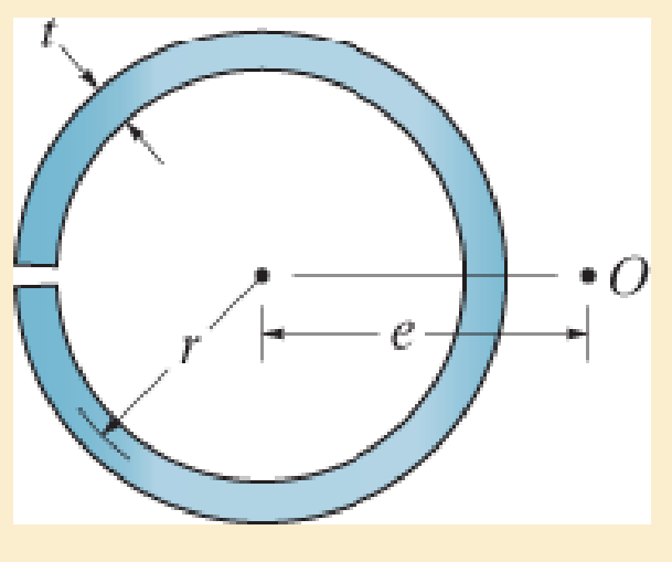
Determine the location e of the shear center, point O, for the tube having a slit along its length.
Expert Solution & Answer
Want to see the full answer?
Check out a sample textbook solution
Students have asked these similar questions
R
αι
g
The system given on the left, consists of three pulleys and
the depicted vertical ropes.
Given:
ri
J₁, m1
R = 2r;
απ
r2, J2, m₂
m1; m2; M3
J1 J2 J3
J3, m3
a) Determine the radii 2 and 3.
B: Solid rotating shaft used in the boat with high speed shown in Figure. The amount of power transmitted at the
greatest torque is 224 kW with 130 r.p.m. Used DE-Goodman theory to determine the shaft diameter. Take the
shaft material is annealed AISI 1030, the endurance limit of 18.86 kpsi and a factor of safety 1. Which criterion
is more conservative?
Note: all dimensions in mm.
1
AA
Motor
300
Thrust
Bearing
Sprocket
100
9750
เอ
Q2: The plate material of a pressure vessel is AISI 1050 QT 205 °C. The plate is rolled to a
diameter of 1.2 m. The two sides of the plate are connected via a riveted joint as shown below. If
the rivet material is G10500 with HB=197 and all rivet sizes M31. Find the required rivet size
when the pressure vessel is subjected to an internal pressure of 500 MPa. Take safety factor = 2.
1.2m
A
B'
A
Chope
olm
10.5
0.23
hope
Chapter 7 Solutions
Mechanics of Materials (10th Edition)
Ch. 7.2 - In each case, calculate the value of Q and t that...Ch. 7.2 - If the beam is subjected to a shear force of V =...Ch. 7.2 - Determine the shear stress at points A and B if...Ch. 7.2 - Determine the absolute maximum shear stress in the...Ch. 7.2 - If the beam is subjected to a shear force of V =20...Ch. 7.2 - If the beam is made from four plates and subjected...Ch. 7.2 - If the wide-flange beam is subjected to a shear of...Ch. 7.2 - If the wide-flange beam is subjected to a shear of...Ch. 7.2 - If the wide-flange beam is subjected to a shear of...Ch. 7.2 - If the beam is subjected to a shear of V = 30 kN,...
Ch. 7.2 - If the wide-flange beam is subjected to a shear of...Ch. 7.2 - The wood beam has an allowable shear stress of...Ch. 7.2 - The shaft is supported by a thrust bearing at A...Ch. 7.2 - The shaft is supported by a thrust bearing at A...Ch. 7.2 - Determine the largest shear force V that the...Ch. 7.2 - If the applied shear force V = 18 kip, determine...Ch. 7.2 - The overhang beam is subjected to the uniform...Ch. 7.2 - The beam is made from a polymer and is subjected...Ch. 7.2 - Determine the maximum shear stress in the strut if...Ch. 7.2 - Determine the maximum shear force V that the strut...Ch. 7.2 - Sketch the intensity of the shear-stress...Ch. 7.2 - Plot the shear-stress distribution over the cross...Ch. 7.2 - If the beam is subjected to a shear of V=15 kN,...Ch. 7.2 - If the wide-flange beam is subjected to a shear of...Ch. 7.2 - If the wide-flange beam is subjected to a shear of...Ch. 7.2 - Determine the length of the cantilevered beam so...Ch. 7.2 - If the beam is made from wood having an allowable...Ch. 7.2 - Determine the largest intensity w of the...Ch. 7.2 - If w=800 lb/ft, determine the absolute maximum...Ch. 7.2 - Determine the shear stress at point B on the web...Ch. 7.2 - Determine the maximum shear stress acting at...Ch. 7.2 - Railroad ties must be designed to resist large...Ch. 7.2 - The beam is slit longitudinally along both sides....Ch. 7.2 - The beam is to be cut longitudinally along both...Ch. 7.2 - The composite beam is constructed from wood and...Ch. 7.2 - The beam has a rectangular cross section and is...Ch. 7.2 - The beam in Fig.6-48f is subjected to a fully...Ch. 7.3 - The two identical boards are bolted together to...Ch. 7.3 - Two identical 20-mm-thick plates are bolted to the...Ch. 7.3 - The boards are bolted together to form the...Ch. 7.3 - The boards are bolted together to form the...Ch. 7.3 - The beam is constructed from two boards fastened...Ch. 7.3 - The beam is constructed from two boards fastened...Ch. 7.3 - The beam is constructed from three boards. If it...Ch. 7.3 - The beam is constructed from three boards....Ch. 7.3 - The double T-beam is fabricated by welding the...Ch. 7.3 - The double T-beam is fabricated by welding the...Ch. 7.3 - The beam is constructed from three boards....Ch. 7.3 - A beam is constructed from three boards bolted...Ch. 7.3 - The simply supported beam is built up from three...Ch. 7.3 - The simply supported beam is built up from three...Ch. 7.3 - The T-beam is constructed as shown. If each nail...Ch. 7.3 - The box beam is constructed from four boards that...Ch. 7.3 - The box beam is constructed from four boards that...Ch. 7.3 - The member consists of two plastic channel strips...Ch. 7.3 - The member consists of two plastic channel strips...Ch. 7.3 - The beam is made from four boards nailed together...Ch. 7.3 - The beam is made from three polystyrene strips...Ch. 7.5 - A shear force of V=300 kN is applied to the box...Ch. 7.5 - A shear force of V=450 kN is applied to the box...Ch. 7.5 - A shear force of V = 18 kN is applied to the box...Ch. 7.5 - A shear force of V = 18 kN is applied to the box...Ch. 7.5 - The aluminum strut is 10 mm thick and has the...Ch. 7.5 - The aluminum strut is 10 mm thick and has the...Ch. 7.5 - The beam is subjected to a shear force of V=50...Ch. 7.5 - The beam is subjected to a shear force of V=50...Ch. 7.5 - The H-beam is subjected to a shear of V=80 kN...Ch. 7.5 - The H-beam is subjected to a shear of V=80 kN...Ch. 7.5 - The built-up beam is formed by welding together...Ch. 7.5 - The assembly is subjected to a vertical shear of V...Ch. 7.5 - The box girder is subjected to a shear of V=15 kN....Ch. 7.5 - Determine the location e of the shear center,...Ch. 7.5 - Determine the location e of the shear center,...Ch. 7.5 - The beam supports a vertical shear of V=7 kip....Ch. 7.5 - The stiffened beam is constructed from plates...Ch. 7.5 - The pipe is subjected to a shear force of V=8 kip....Ch. 7.5 - Determine the location e of the shear center,...Ch. 7.5 - A thin plate of thickness t is bent to form the...Ch. 7.5 - Determine the location e of the shear center,...Ch. 7 - The beam is fabricated from four boards nailed...Ch. 7 - The T-beam is subjected to a shear of V = 150 kN....Ch. 7 - The member is subject to a shear force of V = 2...Ch. 7 - Determine the shear stress at points B and C on...Ch. 7 - Determine the maximum shear stress acting at...
Knowledge Booster


Learn more about
Need a deep-dive on the concept behind this application? Look no further. Learn more about this topic, mechanical-engineering and related others by exploring similar questions and additional content below.Similar questions
- Continuity equation A y x dx D T معادلة الاستمرارية Ly X Q/Prove that ди хе + ♥+ ㅇ? he me ze ོ༞“༠ ?arrow_forwardQ Derive (continuity equation)? I want to derive clear mathematics.arrow_forwardmotor supplies 200 kW at 6 Hz to flange A of the shaft shown in Figure. Gear B transfers 125 W of power to operating machinery in the factory, and the remaining power in the shaft is mansferred by gear D. Shafts (1) and (2) are solid aluminum (G = 28 GPa) shafts that have the same diameter and an allowable shear stress of t= 40 MPa. Shaft (3) is a solid steel (G = 80 GPa) shaft with an allowable shear stress of t = 55 MPa. Determine: a) the minimum permissible diameter for aluminum shafts (1) and (2) b) the minimum permissible diameter for steel shaft (3). c) the rotation angle of gear D with respect to flange A if the shafts have the minimum permissible diameters as determined in (a) and (b).arrow_forward
- First monthly exam Gas dynamics Third stage Q1/Water at 15° C flow through a 300 mm diameter riveted steel pipe, E-3 mm with a head loss of 6 m in 300 m length. Determine the flow rate in pipe. Use moody chart. Q2/ Assume a car's exhaust system can be approximated as 14 ft long and 0.125 ft-diameter cast-iron pipe ( = 0.00085 ft) with the equivalent of (6) regular 90° flanged elbows (KL = 0.3) and a muffler. The muffler acts as a resistor with a loss coefficient of KL= 8.5. Determine the pressure at the beginning of the exhaust system (pl) if the flowrate is 0.10 cfs, and the exhaust has the same properties as air.(p = 1.74 × 10⁻³ slug/ft³, u= 4.7 x 10⁻⁷ lb.s/ft²) Use moody chart (1) MIDAS Kel=0.3 Q3/Liquid ammonia at -20°C is flowing through a 30 m long section of a 5 mm diameter copper tube(e = 1.5 × 10⁻⁶ m) at a rate of 0.15 kg/s. Determine the pressure drop and the head losses. .μ= 2.36 × 10⁻⁴ kg/m.s)p = 665.1 kg/m³arrow_forward2/Y Y+1 2Cp Q1/ Show that Cda Az x P1 mactual Cdf Af R/T₁ 2pf(P1-P2-zxgxpf) Q2/ A simple jet carburetor has to supply 5 Kg of air per minute. The air is at a pressure of 1.013 bar and a temperature of 27 °C. Calculate the throat diameter of the choke for air flow velocity of 90 m/sec. Take velocity coefficient to be 0.8. Assume isentropic flow and the flow to be compressible. Quiz/ Determine the air-fuel ratio supplied at 5000 m altitude by a carburetor which is adjusted to give an air-fuel ratio of 14:1 at sea level where air temperature is 27 °C and pressure is 1.013 bar. The temperature of air decreases with altitude as given by the expression The air pressure decreases with altitude as per relation h = 19200 log10 (1.013), where P is in bar. State any assumptions made. t = ts P 0.0065harrow_forward36 2) Use the method of MEMBERS to determine the true magnitude and direction of the forces in members1 and 2 of the frame shown below in Fig 3.2. 300lbs/ft member-1 member-2 30° Fig 3.2. https://brightspace.cuny.edu/d21/le/content/433117/viewContent/29873977/Viewarrow_forward
- Can you solve this for me?arrow_forward5670 mm The apartment in the ground floor of three floors building in Fig. in Baghdad city. The details of walls, roof, windows and door are shown. The window is a double glazing and air space thickness is 1.3cm Poorly Fitted-with Storm Sash with wood strip and storm window of 0.6 cm glass thickness. The thickness of door is 2.5 cm. The door is Poor Installation. There are two peoples in each room. The height of room is 280 cm. assume the indoor design conditions are 25°C DBT and 50 RH, and moisture content of 8 gw/kga. The moisture content of outdoor is 10.5 gw/kga. Calculate heat gain for living room : الشقة في الطابق الأرضي من مبنى ثلاثة طوابق في مدينة بغداد يظهر في مخطط الشقة تفاصيل الجدران والسقف والنوافذ والباب. النافذة عبارة عن زجاج مزدوج وسمك الفراغ الهوائي 1.3 سم ضعيف الاحكام مع ساتر حماية مع إطار خشبي والنافذة بسماكة زجاج 0.6 سم سماكة الباب 2.5 سم. الباب هو تركيب ضعيف هناك شخصان في كل غرفة. ارتفاع الغرفة 280 سم. افترض أن ظروف التصميم الداخلي هي DBT25 و R50 ، ومحتوى الرطوبة 8…arrow_forwardHow do i solve this problem?arrow_forward
- Q4/ A compressor is driven motor by mean of a flat belt of thickness 10 mm and a width of 250 mm. The motor pulley is 300 mm diameter and run at 900 rpm and the compressor pulley is 1500 mm diameter. The shaft center distance is 1.5 m. The angle of contact of the smaller pulley is 220° and on the larger pulley is 270°. The coefficient of friction between the belt and the small pulley is 0.3, and between the belt and the large pulley is 0.25. The maximum allowable belt stress is 2 MPa and the belt density is 970 kg/m³. (a) What is the power capacity of the drive and (b) If the small pulley replaced by V-grooved pulley of diameter 300 mm, grooved angle of 34° and the coefficient of friction between belt and grooved pulley is 0.35. What will be the power capacity in this case, assuming that the diameter of the large pulley remain the same of 1500 mm.arrow_forwardYou are tasked with designing a power drive system to transmit power between a motor and a conveyor belt in a manufacturing facility as illustrated in figure. The design must ensure efficient power transmission, reliability, and safety. Given the following specifications and constraints, design drive system for this application: Specifications: Motor Power: The electric motor provides 10 kW of power at 1,500 RPM. Output Speed: The output shaft should rotate at 150 rpm. Design Decisions: Transmission ratio: Determine the necessary drive ratio for the system. Shaft Diameter: Design the shafts for both the motor and the conveyor end. Material Selection: Choose appropriate materials for the gears, shafts. Bearings: Select suitable rolling element bearings. Constraints: Space Limitation: The available space for the gear drive system is limited to a 1-meter-long section. Attribute 4 of CEP Depth of knowledge required Fundamentals-based, first principles analytical approach…arrow_forward- | العنوان In non-continuous dieless drawing process for copper tube as shown in Fig. (1), take the following data: Do-20mm, to=3mm, D=12mm, ti/to=0.6 and v.-15mm/s. Calculate: (1) area reduction RA, (2) drawing velocity v. Knowing that: ti: final thickness V. Fig. (1) ofthrearrow_forward
arrow_back_ios
SEE MORE QUESTIONS
arrow_forward_ios
Recommended textbooks for you
 International Edition---engineering Mechanics: St...Mechanical EngineeringISBN:9781305501607Author:Andrew Pytel And Jaan KiusalaasPublisher:CENGAGE L
International Edition---engineering Mechanics: St...
Mechanical Engineering
ISBN:9781305501607
Author:Andrew Pytel And Jaan Kiusalaas
Publisher:CENGAGE L
Everything About TRANSVERSE SHEAR in 10 Minutes!! - Mechanics of Materials; Author: Less Boring Lectures;https://www.youtube.com/watch?v=4x0E9yvzfCM;License: Standard Youtube License