
Mechanics of Materials (10th Edition)
10th Edition
ISBN: 9780134319650
Author: Russell C. Hibbeler
Publisher: PEARSON
expand_more
expand_more
format_list_bulleted
Videos
Textbook Question
Chapter 7.5, Problem 7.50P
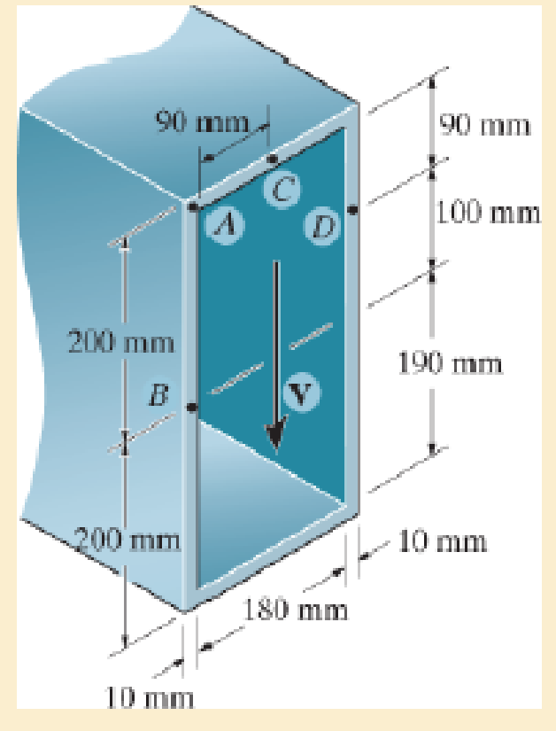
A shear force of V=300 kN is applied to the box girder. Determine the shear flow at points A and B.
Probs. 7–50/51
Expert Solution & Answer
Want to see the full answer?
Check out a sample textbook solution
Students have asked these similar questions
Show work on how to obtain P2 and T2. If using any table, please refer to it. If applying interpolation method, please show the work.
cast-iron roller
FIGURE P11-3
Shaft Design for Problems 11-17
Chapter 11
BEARINGS AND LUBRICATION
677
gear
key
P
assume bearings act
as simple supports
11-18 Problem 7-18 determined the half-width of the contact patch for a 1.575-in-dia steel
cylinder, 9.843 in long, rolled against a flat aluminum plate with 900 lb of force to be
0.0064 in. If the cylinder rolls at 800 rpm, determine its lubrication condition with ISO
VG 1000 oil at 200°F. R₁ = 64 μin (cylinder); R₁ = 32 μin (plate).
11-19 The shaft shown in Figure P11-4 was designed in Problem 10-19. For the data in the
row(s) assigned from Table P11-1, and the corresponding diameter of shaft found in
Problem 10-19, design suitable bearings to support the load for at least 5E8 cycles at
1200 rpm. State all assumptions.
(a)
(b)
Using hydrodynamically lubricated bronze sleeve bearings with ON = 40,
1/ d=0.80, and a clearance ratio of 0.002 5.
Using deep-groove ball bearings for a 10% failure rate.
*11-20 Problem 7-20 determined the…
Calculate the shear force at the point D on the beam below. Take F=19 and remember that
this quantity is to be used to calculate both forces and lengths.
15F
A
с
Chapter 7 Solutions
Mechanics of Materials (10th Edition)
Ch. 7.2 - In each case, calculate the value of Q and t that...Ch. 7.2 - If the beam is subjected to a shear force of V =...Ch. 7.2 - Determine the shear stress at points A and B if...Ch. 7.2 - Determine the absolute maximum shear stress in the...Ch. 7.2 - If the beam is subjected to a shear force of V =20...Ch. 7.2 - If the beam is made from four plates and subjected...Ch. 7.2 - If the wide-flange beam is subjected to a shear of...Ch. 7.2 - If the wide-flange beam is subjected to a shear of...Ch. 7.2 - If the wide-flange beam is subjected to a shear of...Ch. 7.2 - If the beam is subjected to a shear of V = 30 kN,...
Ch. 7.2 - If the wide-flange beam is subjected to a shear of...Ch. 7.2 - The wood beam has an allowable shear stress of...Ch. 7.2 - The shaft is supported by a thrust bearing at A...Ch. 7.2 - The shaft is supported by a thrust bearing at A...Ch. 7.2 - Determine the largest shear force V that the...Ch. 7.2 - If the applied shear force V = 18 kip, determine...Ch. 7.2 - The overhang beam is subjected to the uniform...Ch. 7.2 - The beam is made from a polymer and is subjected...Ch. 7.2 - Determine the maximum shear stress in the strut if...Ch. 7.2 - Determine the maximum shear force V that the strut...Ch. 7.2 - Sketch the intensity of the shear-stress...Ch. 7.2 - Plot the shear-stress distribution over the cross...Ch. 7.2 - If the beam is subjected to a shear of V=15 kN,...Ch. 7.2 - If the wide-flange beam is subjected to a shear of...Ch. 7.2 - If the wide-flange beam is subjected to a shear of...Ch. 7.2 - Determine the length of the cantilevered beam so...Ch. 7.2 - If the beam is made from wood having an allowable...Ch. 7.2 - Determine the largest intensity w of the...Ch. 7.2 - If w=800 lb/ft, determine the absolute maximum...Ch. 7.2 - Determine the shear stress at point B on the web...Ch. 7.2 - Determine the maximum shear stress acting at...Ch. 7.2 - Railroad ties must be designed to resist large...Ch. 7.2 - The beam is slit longitudinally along both sides....Ch. 7.2 - The beam is to be cut longitudinally along both...Ch. 7.2 - The composite beam is constructed from wood and...Ch. 7.2 - The beam has a rectangular cross section and is...Ch. 7.2 - The beam in Fig.6-48f is subjected to a fully...Ch. 7.3 - The two identical boards are bolted together to...Ch. 7.3 - Two identical 20-mm-thick plates are bolted to the...Ch. 7.3 - The boards are bolted together to form the...Ch. 7.3 - The boards are bolted together to form the...Ch. 7.3 - The beam is constructed from two boards fastened...Ch. 7.3 - The beam is constructed from two boards fastened...Ch. 7.3 - The beam is constructed from three boards. If it...Ch. 7.3 - The beam is constructed from three boards....Ch. 7.3 - The double T-beam is fabricated by welding the...Ch. 7.3 - The double T-beam is fabricated by welding the...Ch. 7.3 - The beam is constructed from three boards....Ch. 7.3 - A beam is constructed from three boards bolted...Ch. 7.3 - The simply supported beam is built up from three...Ch. 7.3 - The simply supported beam is built up from three...Ch. 7.3 - The T-beam is constructed as shown. If each nail...Ch. 7.3 - The box beam is constructed from four boards that...Ch. 7.3 - The box beam is constructed from four boards that...Ch. 7.3 - The member consists of two plastic channel strips...Ch. 7.3 - The member consists of two plastic channel strips...Ch. 7.3 - The beam is made from four boards nailed together...Ch. 7.3 - The beam is made from three polystyrene strips...Ch. 7.5 - A shear force of V=300 kN is applied to the box...Ch. 7.5 - A shear force of V=450 kN is applied to the box...Ch. 7.5 - A shear force of V = 18 kN is applied to the box...Ch. 7.5 - A shear force of V = 18 kN is applied to the box...Ch. 7.5 - The aluminum strut is 10 mm thick and has the...Ch. 7.5 - The aluminum strut is 10 mm thick and has the...Ch. 7.5 - The beam is subjected to a shear force of V=50...Ch. 7.5 - The beam is subjected to a shear force of V=50...Ch. 7.5 - The H-beam is subjected to a shear of V=80 kN...Ch. 7.5 - The H-beam is subjected to a shear of V=80 kN...Ch. 7.5 - The built-up beam is formed by welding together...Ch. 7.5 - The assembly is subjected to a vertical shear of V...Ch. 7.5 - The box girder is subjected to a shear of V=15 kN....Ch. 7.5 - Determine the location e of the shear center,...Ch. 7.5 - Determine the location e of the shear center,...Ch. 7.5 - The beam supports a vertical shear of V=7 kip....Ch. 7.5 - The stiffened beam is constructed from plates...Ch. 7.5 - The pipe is subjected to a shear force of V=8 kip....Ch. 7.5 - Determine the location e of the shear center,...Ch. 7.5 - A thin plate of thickness t is bent to form the...Ch. 7.5 - Determine the location e of the shear center,...Ch. 7 - The beam is fabricated from four boards nailed...Ch. 7 - The T-beam is subjected to a shear of V = 150 kN....Ch. 7 - The member is subject to a shear force of V = 2...Ch. 7 - Determine the shear stress at points B and C on...Ch. 7 - Determine the maximum shear stress acting at...
Knowledge Booster


Learn more about
Need a deep-dive on the concept behind this application? Look no further. Learn more about this topic, mechanical-engineering and related others by exploring similar questions and additional content below.Similar questions
- "II-1 The shaft shown in Figure P11-I was designed in Problem 10-1. For the data in the row(s) assigned from Table P11-1, and the corresponding diameter of shaft found in Problem 10-1, design suitable bearings to support the load for at least 7E7 cycles at 1500 rpm. State all assumptions. (a) Using hydrodynamically lubricated bronze sleeve bearings with Ox = 20, 1/d=1.25, and a clearance ratio of 0.001 5. assume bearings act as simple supports FIGURE P11-1 Shaft Design for Problem 11-1 11-2 The shaft shown in Figure P11-2 was designed in Problem 10-2. For the data in the row(s) assigned from Table P11-1, and the corresponding diameter of shaft found in Problem 10-2, design suitable bearings to support the load for at least 3E8 cycles at 2.500 rpm. State all assumptions. (a) Using hydrodynamically lubricated bronze sleeve bearings with ON=30, 1/d=1.0, and a clearance ratio of 0.002. FIGURE P11-2 Shaft Design for Problem 11-2 Table P11-1 Data for Problems assume bearings act as simple…arrow_forwardFor the frame below, calculate the shear force at point Q. Take P=13 and note that this value is used for both the loads and the lengths of the members of the frame. 1 A Q ✗ 19 KBP 2.5P- B R C 45 degrees ✗ 1 .2P- 4PhN -P→arrow_forwardCalculate the Bending Moment at point D in the frame below. Leave your answer in Nm (newton-metres) J J A 2m 2m <2m х D 不 1m X E 5m 325 Nm 4x 400N/marrow_forward
- In the beam below, calculate the shear force at point A. Take L=78 and remember that both the loads and the dimensions are expressed in terms of L. 143 1 DX A - Li 4 LhN 14LRN/m Х B 22 3 L.arrow_forwardCalculate the Shear Force at Point F on the beam below. Keep your answer in Newtons and make shear force positive to the right. A х 2m <2m E D 5m 1m Хт 325N1m 400N/m 8arrow_forwardThe normal force at C on the beam below is equal to: A ShN C X 15h N 8 ○ OkN 2.5kN 10kN ○ 12.5kN 1m Im 1m 1m;arrow_forward
- Calculate the y coordinate of the of the centroid of the shape below. Take A= 18.5 8 6A 4A X 6Aarrow_forwardIn MATLAB write out a program to integrate the equations of motion of a rigid body. The inertia matrix is given by I = [125 0 0; 0 100 0; 0 0 75] which is a diagonal, where diag operator provides a matrix with given elements placed on its diagonal. Consider three cases where the body rotates 1 rad/sec about each principal axis. Integrate the resulting motion and study the angular rates and the resulting attitude (use any attitude coordinates). For each principal axis case, assume first that a pure spin about the principal axis is performed, and then repeat the simulation where a small 0.1 rad/sec motion is present about another principal axis. Discuss the stability of each motion. The code should produce a total of 6 simulations results when it is ran.arrow_forwardQ. A strain gauge rosette that is attached to the surface of a stressed component C). If the strain gauge rosette is of the D° gives 3 readings (a = A, b = B, &c = type (indicating the angle between each of the gauges), construct a Mohr's Strain Circle overleaf. You should assume that gauge A is aligned along the x-axis. Using the Mohr's Strain Circle calculate the: [10 marks] 100 918 ucy evods gringiz ya mwo quoy al etsede 39 926919 (i) principal strains (1, 2)? (au) oniona [5 marks] (ii) principal angles (1, 2)? You should measure these anticlockwise from the y-axis. 20 [5 marks] (iii) maximum shear strain in the plane (ymax)? Ex = Ea Ey = εc [5 marks] (epol) (apob) é Ea = A = -210 2 B=E₁ = -50 E₁ = C = 340 D = 45° bril elled ✓A bedivordan nemigas olloho shot on no eonsoup Imeneo alubom shine sail-no viss ieqse sidetiva bnat sabied 2arrow_forward
- 1) Solve and show which is converage or diyverage a = 2+(0.1)" 3 16) a = n 1-2n 2) a = In n 1+2n 17) a = n 1-5n4 3) an = n* +8n³ 18) a =√4"n n² -2n+1 n! 20) a = 4) a₁ = 10 n-1 (Ina) 5) a=1+(-1)" 21) a= 6) a 7) an = * = (12+) (1-1) 2n (-1)+1 2n-1 3n+1 22) a= 3n-1 x" 23) a= .x>0 2n+1 2n 3"x6" 8) a = 24) a = n+1 π 9) a = sin 2 sin n 10) an = n + 2 x n! 25) a = tanh(n) n² 1 26) a = -sin- 2n-1 27) a = tan(n) n n 11) a = 2" 12) a = n 13) a = 8/ +=(1+2)" 14) a = 15) a = √10n In(n+1) 29) a = n 30) an-√n²-1 1 28) a = + √2" (In n)200 n 31) a=- = 1 dx nixarrow_forwardHW12 A multiple-disc clutch has five plates having four pairs of active friction surfaces. If the intensity of pressure is not to exceed 0.127 N/mm², find the power transmitted at 500 r.p.m. The outer and inner radii of friction surfaces are 125 mm and 75 mm respectively. Assume uniform wear and take the coefficient of friction = 0.3.arrow_forwardThe sketch below gives some details of the human heart at rest. What is the total power requirement (work/time) for an artificial heart pump if we use a safety factor of 5 to allow for inefficiencies, the need to operate the heart under stress, etc.? Assume blood has the properties of water. p pressure above atmosphere blood going to the lungs for a fresh charge of oxygen p = 2.9 kPa 25v pulmonary artery d = 25mm fresh oxygenated blood from the lungs p = 1.0 kPa vena cava d=30mm right auricle pulmonary vein, d = 28mm aorta, d=20mm spent blood returning from left auricle the body p = 0.66 kPa right left ventricle ventricle blood to feed the body, p 13 kPa normal blood flow = 90 ml/sarrow_forward
arrow_back_ios
SEE MORE QUESTIONS
arrow_forward_ios
Recommended textbooks for you
 Elements Of ElectromagneticsMechanical EngineeringISBN:9780190698614Author:Sadiku, Matthew N. O.Publisher:Oxford University Press
 Mechanics of Materials (10th Edition)Mechanical EngineeringISBN:9780134319650Author:Russell C. HibbelerPublisher:PEARSON
 Thermodynamics: An Engineering ApproachMechanical EngineeringISBN:9781259822674Author:Yunus A. Cengel Dr., Michael A. BolesPublisher:McGraw-Hill Education
 Control Systems EngineeringMechanical EngineeringISBN:9781118170519Author:Norman S. NisePublisher:WILEY
 Mechanics of Materials (MindTap Course List)Mechanical EngineeringISBN:9781337093347Author:Barry J. Goodno, James M. GerePublisher:Cengage Learning
 Engineering Mechanics: StaticsMechanical EngineeringISBN:9781118807330Author:James L. Meriam, L. G. Kraige, J. N. BoltonPublisher:WILEY
Elements Of Electromagnetics
Mechanical Engineering
ISBN:9780190698614
Author:Sadiku, Matthew N. O.
Publisher:Oxford University Press
Mechanics of Materials (10th Edition)
Mechanical Engineering
ISBN:9780134319650
Author:Russell C. Hibbeler
Publisher:PEARSON
Thermodynamics: An Engineering Approach
Mechanical Engineering
ISBN:9781259822674
Author:Yunus A. Cengel Dr., Michael A. Boles
Publisher:McGraw-Hill Education
Control Systems Engineering
Mechanical Engineering
ISBN:9781118170519
Author:Norman S. Nise
Publisher:WILEY
Mechanics of Materials (MindTap Course List)
Mechanical Engineering
ISBN:9781337093347
Author:Barry J. Goodno, James M. Gere
Publisher:Cengage Learning
Engineering Mechanics: Statics
Mechanical Engineering
ISBN:9781118807330
Author:James L. Meriam, L. G. Kraige, J. N. Bolton
Publisher:WILEY
Everything About TRANSVERSE SHEAR in 10 Minutes!! - Mechanics of Materials; Author: Less Boring Lectures;https://www.youtube.com/watch?v=4x0E9yvzfCM;License: Standard Youtube License