
Engineering Mechanics: Statics & Dynamics (14th Edition)
14th Edition
ISBN: 9780133915426
Author: Russell C. Hibbeler
Publisher: PEARSON
expand_more
expand_more
format_list_bulleted
Concept explainers
Videos
Textbook Question
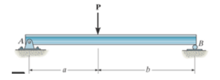
Chapter 7.2, Problem 47P
Draw the shear and moment diagrams for the beam (a) in terms of the parameters shown; (b) set P = 6001b, a = 5ft, b = 7ft.
Expert Solution & Answer
Want to see the full answer?
Check out a sample textbook solution
Students have asked these similar questions
5. Draw the shear force for the beam shown. Label all significant points on the diagram and clearly
distinguish straight-line and curve portions of the diagram. The ground reactions are Ay = 340 kN
upward, Cx = 0 and Cy = 620 kN upward
160 kN
120 kN/m
50 kN/m
C
-5 m-
-2 m-
-2 m
Use the graphical method to construct the shear-force and bending-moment diagrams for the beam shown. Let a = 2.2 m, b = 4.4 m, c = 3 m, P = 16 kN, w = 34 kN/m, and Q = 26 kN. Label all significant points on each diagram and identify the maximum shear force and bending moment along with their respective locations. Additionally:(a) Determine V and M in the beam at a point located 0.65 m to the right of B.(b) Determine V and M in the beam at a point located 1.40 m to the left of C.Note that answers may be positive or negative. Here, "maximum" refers to the largest magnitude value, but you should enter your shear force and bending moment with the correct sign, using the sign convention presented in Section 7.2 of the textbook. If the magnitudes of the largest positive and largest negative values are the same, enter a positive number.
Use the graphical method to construct the shear-force and bending-moment diagrams for the beam shown. Let a = 3.8 m, b = 7.6 m, c =
5.1 m, P = 11 kN, w = 41 kN/m, and Q = 29 kN. Label all significant points on each diagram and identify the maximum shear force and
bending moment along with their respective locations. Additionally:
(a) Determine V and M in the beam at a point located 0.50 m to the right of B.
(b) Determine V and M in the beam at a point located 1.15 m to the left of C.
Note that answers may be positive or negative. Here, "maximum" refers to the largest magnitude value, but you should enter your
shear force and bending moment with the correct sign, using the sign convention presented in Section 7.2 of the textbook. If the
magnitudes of the largest positive and largest negative values are the same, enter a positive number.
В
a
b
Answer:
Vmax
kN
Mmax
kN•m
(a) Vx1=
kN
Mx1 =
kN•m
(b) Vx2 =
kN
Mx2 =
kN•m
Chapter 7 Solutions
Engineering Mechanics: Statics & Dynamics (14th Edition)
Ch. 7.1 - In each case, calculate the reaction at A and then...Ch. 7.1 - Determine the normal force, shear force, and...Ch. 7.1 - Determine the normal force, shear force, and...Ch. 7.1 - Determine the normal force, shear force, and...Ch. 7.1 - Determine the normal force, shear force, and...Ch. 7.1 - Determine the normal force, shear force, and...Ch. 7.1 - Determine the normal force, shear force, and...Ch. 7.1 - Determine the shear force and moment at points C...Ch. 7.1 - Determine the internal normal force and shear...Ch. 7.1 - Two beams are attached to the column such that...
Ch. 7.1 - The beam weighs 280 lb/ft. Determine the internal...Ch. 7.1 - The pliers are used to grip the tube at B. If a...Ch. 7.1 - Determine the distance a as a fraction of the...Ch. 7.1 - Determine the internal shear force and moment...Ch. 7.1 - Determine the internal shear force and moment...Ch. 7.1 - Determine the normal force, shear force, and...Ch. 7.1 - The cable will fail when subjected to a tension of...Ch. 7.1 - Determine the internal normal force, shear force,...Ch. 7.1 - Determine the distance a between the bearings in...Ch. 7.1 - Determine the internal normal force, shear force,...Ch. 7.1 - The shaft is supported by a journal bearing at A...Ch. 7.1 - Determine the internal normal force, shear force,...Ch. 7.1 - Determine the internal normal force, shear force,...Ch. 7.1 - The cantilevered rack is used to support each end...Ch. 7.1 - Determine the internal normal force, shear force,...Ch. 7.1 - Determine the internal normal force, shear force,...Ch. 7.1 - Rod AB is fixed to a smooth collar D, which slides...Ch. 7.1 - Determine the internal normal force, shear force,...Ch. 7.1 - Determine the internal normal force, shear force,...Ch. 7.1 - Determine the internal normal force, shear force,...Ch. 7.1 - Determine the ratio of a/b for which the shear...Ch. 7.1 - Determine the normal force, shear force, and...Ch. 7.1 - Determine the internal normal force, shear force,...Ch. 7.1 - Determine the internal normal force, shear force,...Ch. 7.1 - Determine the internal normal force, shear force,...Ch. 7.1 - Determine the normal force, shear force, and...Ch. 7.1 - Determine the normal force, shear force, and...Ch. 7.1 - Determine the internal normal force, shear force,...Ch. 7.1 - Determine the internal normal force, shear force,...Ch. 7.1 - Determine the internal normal force, shear force,...Ch. 7.1 - Determine the internal normal force, shear force,...Ch. 7.1 - The strongback or lifting beam is used for...Ch. 7.1 - Determine the internal normal force, shear force,...Ch. 7.1 - Determine the internal normal force, shear force,...Ch. 7.1 - Determine the internal normal force, shear force,...Ch. 7.1 - The distributed loading W = W0 sin , measured per...Ch. 7.1 - Solve Prob. 7-39 for = 120. Probs. 739/40Ch. 7.1 - Determine the x, y. z components of force and...Ch. 7.1 - Determine the x, y, z components of force and...Ch. 7.1 - Determine the x, y, z components of internal...Ch. 7.1 - Determine the x, y. z components of internal...Ch. 7.2 - Determine the shear and moment as a function of x,...Ch. 7.2 - Determine the shear and moment as a function of x,...Ch. 7.2 - Determine the shear and moment as a function of x,...Ch. 7.2 - Determine the shear and moment as a function of x,...Ch. 7.2 - Determine the shear and moment as a function of x,...Ch. 7.2 - Determine the shear and moment as a function of x,...Ch. 7.2 - Draw the shear and moment diagrams for the shaft...Ch. 7.2 - Draw the shear and moment diagrams for the beam...Ch. 7.2 - Draw the shear and moment diagrams for the beam...Ch. 7.2 - Draw the shear and moment diagrams for the...Ch. 7.2 - Draw the shear and moment diagrams of the beam (a)...Ch. 7.2 - If L = 9 m, the beam will fail when the maximum...Ch. 7.2 - Draw the shear and moment diagrams for the beam....Ch. 7.2 - Draw the shear and moment diagrams for the beam....Ch. 7.2 - Draw the shear and bending-moment diagrams for the...Ch. 7.2 - The shaft is supported by a smooth thrust bearing...Ch. 7.2 - Draw the shear and moment diagrams for the beam....Ch. 7.2 - Draw the shear and moment diagrams for the beam....Ch. 7.2 - Draw the shear and moment diagrams for the...Ch. 7.2 - Draw the shear and bending-moment diagrams for...Ch. 7.2 - Draw the shear and moment diagrams for the beam....Ch. 7.2 - The shaft is supported by a smooth thrust bearing...Ch. 7.2 - Draw the shear and moment diagrams for the beam....Ch. 7.2 - The beam will fail when the maximum internal...Ch. 7.2 - Prob. 63PCh. 7.2 - Prob. 64PCh. 7.2 - Prob. 65PCh. 7.2 - Draw the shear and moment diagrams for the beam....Ch. 7.2 - Determine the internal normal force, shear force,...Ch. 7.2 - The quarter circular rod lies in the horizontal...Ch. 7.2 - Express the internal shear and moment components...Ch. 7.3 - Draw the shear and moment diagrams for the beam....Ch. 7.3 - Draw the shear and moment diagrams for the beam....Ch. 7.3 - Draw the shear and moment diagrams for the beam....Ch. 7.3 - Draw the shear and moment diagrams for the beam....Ch. 7.3 - Draw the shear and moment diagrams for the beam....Ch. 7.3 - Draw the shear and moment diagrams for the beam....Ch. 7.3 - Draw the shear and moment diagrams for the beam....Ch. 7.3 - Draw the shear and moment diagrams for the beam....Ch. 7.3 - Draw the shear and moment diagrams for the beam....Ch. 7.3 - Draw the shear and moment diagrams for the...Ch. 7.3 - Draw the shear and moment diagrams for the beam....Ch. 7.3 - Draw the shear and moment diagrams for the beam....Ch. 7.3 - Draw the shear and moment diagrams for the beam....Ch. 7.3 - Draw the shear and moment diagrams for the beam....Ch. 7.3 - Draw the shear and moment diagrams for the beam....Ch. 7.3 - Draw the shear and moment diagrams for the shaft....Ch. 7.3 - Draw the shear and moment diagrams for the beam....Ch. 7.3 - The beam consists of three segments pin connected...Ch. 7.3 - Draw the shear and moment diagrams for the beam....Ch. 7.3 - Draw the shear and moment diagrams for the beam....Ch. 7.3 - Draw the shear and moment diagrams for the beam....Ch. 7.3 - Draw the shear and moment diagrams for the beam....Ch. 7.3 - Draw the shear and moment diagrams for the beam....Ch. 7.3 - Draw the shear and moment diagrams for the beam....Ch. 7.3 - Draw the shear and moment diagrams for the beam....Ch. 7.3 - Draw the shear and moment diagrams for the beam....Ch. 7.3 - Draw the shear and moment diagrams for the beam....Ch. 7.3 - Draw the shear and moment diagrams for the beam....Ch. 7.3 - Draw the shear and moment diagrams for the beam....Ch. 7.3 - Draw the shear and moment diagrams for the beam....Ch. 7.4 - The cable supports the three loads shown....Ch. 7.4 - Prob. 95PCh. 7.4 - Determine the tension in each segment of the cable...Ch. 7.4 - Prob. 97PCh. 7.4 - The cable supports the loading shown. Determine...Ch. 7.4 - The cable supports the three loads shown....Ch. 7.4 - The cable supports the three loads shown....Ch. 7.4 - Determine the force P needed to hold the cable in...Ch. 7.4 - Determine the maximum uniform loading w, measured...Ch. 7.4 - The cable is subjected to a uniform loading of w =...Ch. 7.4 - The cable AB is subjected to a uniform loading of...Ch. 7.4 - If x = 2 ft and the crate weighs 300 lb, which...Ch. 7.4 - If yB = 1.5 ft. determine the largest weight of...Ch. 7.4 - The cable supports a girder which weighs 850...Ch. 7.4 - The cable is subjected to a uniform loading of w =...Ch. 7.4 - If the pipe has a mass per unit length of 1500...Ch. 7.4 - Prob. 110PCh. 7.4 - Prob. 111PCh. 7.4 - The cable will break when the maximum tension...Ch. 7.4 - Prob. 113PCh. 7.4 - The power transmission cable weighs 10 lb/fl. If...Ch. 7.4 - Prob. 115PCh. 7.4 - Prob. 116PCh. 7.4 - Prob. 117PCh. 7.4 - Prob. 118PCh. 7.4 - Show that the deflection curve of the cable...Ch. 7.4 - Prob. 120PCh. 7.4 - Prob. 121PCh. 7.4 - Prob. 122PCh. 7.4 - A cable has a weight of 5 lb/ft. If it can span...Ch. 7.4 - The 10 kg/m cable is suspended between the...Ch. 7.4 - Determine the internal normal force, shear force,...Ch. 7.4 - Prob. 2RPCh. 7.4 - Prob. 3RPCh. 7.4 - Prob. 4RPCh. 7.4 - Draw the shear and moment diagrams for the beam....Ch. 7.4 - A chain is suspended between points at the same...
Knowledge Booster


Learn more about
Need a deep-dive on the concept behind this application? Look no further. Learn more about this topic, mechanical-engineering and related others by exploring similar questions and additional content below.Similar questions
- SHEAR AND MOMENT DIAGRAM PROBLEM 2 Use the AREA method to construct the shear-force and bending-moment diagrams for the beam shown. Let a = 6.9 ft, b = 10.4 ft, c = 5.8 ft, and w = 9.5 kips/ft. Label all significant points on each diagram and identify the maximum moments (both positive and negative) along with their respective locations. Clearly differentiate straight-line and curved portions of the diagrams. Determine the maximum shear force and bending moment in the beam. Note that answers may be positive or negative. Here, "maximum" refers to the largest magnitude value, but you should enter your shear force and bending moment with the correct sign, using the sign convention. If the magnitudes of the largest positive and largest negative values are the same, enter a positive number. The roller at point D indicates that motion is restricted both up and down, and the beam will not lift off the roller. a B W b C D Xarrow_forwardSHEAR AND MOMENT DIAGRAM PROBLEM 2 Use the AREA method to construct the shear-force and bending-moment diagrams for the beam shown. Let a = 6.9 ft, b = 10.4 ft, c = 5.8 ft, and w = 9.5 kips/ft. Label all significant points on each diagram and identify the maximum moments (both positive and negative) along with their respective locations. Clearly differentiate straight-line and curved portions of the diagrams. Determine the maximum shear force and bending moment in the beam. Note that answers may be positive or negative. Here, "maximum" refers to the largest magnitude value, but you should enter your shear force and bending moment with the correct sign, using the sign convention. If the magnitudes of the largest positive and largest negative values are the same, enter a positive number. The roller at point D indicates that motion is restricted both up and down, and the beam will not lift off the roller. a B W b O D Xarrow_forward3 For the beam shown, find the reactions at the supports and plot the shear-force and bending-moment diagrams. V = 9 kN, V2 = 9 kN, V3 = 200 mm, and V4 = 1100 mm. ATAT-V3 Provide values at all key points shown in the given shear-force and bending-moment diagrams. X (mm) B A = B = C = D = E= F= P = Q = E * KN * KN * KN × KN KN x KN ✩ kN.mm *kN.mm D 0.00 Reaction force R₁ (left) = In the shear-force and bending-moment diagrams given, +V 0.00 X (mm) 6.3 kN and reaction force R2 (right) = P 11.7 kN. Q 0.00arrow_forward
- Construct the shear and moment diagrams for the loaded beam shown. After you have the diagrams, answer the questions. *+ °m = m- 4.7 kN/m 2.0 kN/m B 4.6 m Questions: At x = 1.1 m, V = kN, M= i kN-m Atx = 3.8 m, V= kN, M= kN-m The absolute value of the maximum shear force Vmax= at x kN, i i is The absolute value of the maximum bending Mmax at x kN-m, i moment is Earrow_forward10 lb/ft B 5 ft 3 ft Ay = 25 lb By = 25 lb %3Darrow_forwardFor the simply supported beam subjected to the loading shown, derive equations for the shear force V and the bending moment M for any location in the beam. Place the origin at point A. Let a=4.00 m, b=5.25 m, c= 2.50 m, P = 26kN and M = 160kN-m. Construct the shear-force and bending-moment diagrams. Use the bending-moment diagram to determine the maximum positive bending moment, Mmax, pos, and the maximum negative bending moment, Mmax, neg.arrow_forward
- The cantilever beam carries a uniformly varying load as shown. In addition, a 1000 lb-upwardvertical load acts at the free end of the beam. Derive the shear force and bending momentequations and draw the shear force and bending moment diagrams. Neglect the weight of thebeamarrow_forwardThe figure below shows a horizontal beam of uniform cross-section, rigidly built-in at each end and having a 10 m long clear span. The beam is loaded as shown. Draw the shear force and bending moment diagrams and determine the point(s) of contraflexture. 40 kN 32 kN 32 kN 40 kN 25 kN/m 2 m 2 m 2 m 2 m 2 marrow_forwardFor the beam and loading shown, write the equations for the internal shear force V and bending moment M as a function of x and then draw the shear and moment diagrams. Also, state the values of the internal shear force and bending moment at x = 1.4 m and x = 4.9 m. [Answer: At x = 1.4 m, V = 8.51 kN and M = -23.5 kN m and at x = 4.9 m, V = 2.93 kN and M = -2.77 kN m]arrow_forward
- Draw the shear diagram for the beam. Set Mo = 500 N⋅m, L = 8 m. Draw the moment diagram for the beam. Set Mo = 500 N⋅m, L = 8 m.arrow_forwardPlot the shear and moment diagrams for the beam subjected to the concentrated force and distributed load. Then answer the questions to check your work. Assume w₁ = 3.1 kN/m, w2 = 2.0 kN/m, F = 8.0 kN, a = 13 m, b = 3m. W A Questions: k W = Wo - kx³/2 F พ, B b- -x When x = 4.2 m, V = KN M= i kN-m When x = 14.9 m, V = kN M= <- d kN-marrow_forwardUse the graphical method to construct the shear-force and bending-moment diagrams for the beam shown. Let a=4.0 m, b=2.5 m, PB = 4 kN, PC = 4 kN, and MB = 60 kN-m. Construct the shear-force and bending-moment diagrams on paper and use the results to answer the questions in the subsequent parts of this GO exercise.Calculate the reaction forces Ay and MA acting on the beam. Positive values for the reactions are indicated by the directions of the red arrows shown on the free-body diagram below. (Note: Since Ax = 0, it has been omitted from the free-body diagram.) Determine the bending moment acting at each of the following locations:(a) x = 0+ m (i.e., just to the right of fixed support A)(b) x = 4.0– m (i.e., just to the left of B)(c) x = 4.0+ m (i.e., just to the right of B)(d) x = 6.5 mWhen entering your answers, use the bending moment sign convention.Answers:(a) M = kN-m.(b) M = kN-m.(c) M = kN-m.(d) M = kN-m.arrow_forward
arrow_back_ios
SEE MORE QUESTIONS
arrow_forward_ios
Recommended textbooks for you
 Elements Of ElectromagneticsMechanical EngineeringISBN:9780190698614Author:Sadiku, Matthew N. O.Publisher:Oxford University Press
 Mechanics of Materials (10th Edition)Mechanical EngineeringISBN:9780134319650Author:Russell C. HibbelerPublisher:PEARSON
 Thermodynamics: An Engineering ApproachMechanical EngineeringISBN:9781259822674Author:Yunus A. Cengel Dr., Michael A. BolesPublisher:McGraw-Hill Education
 Control Systems EngineeringMechanical EngineeringISBN:9781118170519Author:Norman S. NisePublisher:WILEY
 Mechanics of Materials (MindTap Course List)Mechanical EngineeringISBN:9781337093347Author:Barry J. Goodno, James M. GerePublisher:Cengage Learning
 Engineering Mechanics: StaticsMechanical EngineeringISBN:9781118807330Author:James L. Meriam, L. G. Kraige, J. N. BoltonPublisher:WILEY
Elements Of Electromagnetics
Mechanical Engineering
ISBN:9780190698614
Author:Sadiku, Matthew N. O.
Publisher:Oxford University Press
Mechanics of Materials (10th Edition)
Mechanical Engineering
ISBN:9780134319650
Author:Russell C. Hibbeler
Publisher:PEARSON
Thermodynamics: An Engineering Approach
Mechanical Engineering
ISBN:9781259822674
Author:Yunus A. Cengel Dr., Michael A. Boles
Publisher:McGraw-Hill Education
Control Systems Engineering
Mechanical Engineering
ISBN:9781118170519
Author:Norman S. Nise
Publisher:WILEY
Mechanics of Materials (MindTap Course List)
Mechanical Engineering
ISBN:9781337093347
Author:Barry J. Goodno, James M. Gere
Publisher:Cengage Learning
Engineering Mechanics: Statics
Mechanical Engineering
ISBN:9781118807330
Author:James L. Meriam, L. G. Kraige, J. N. Bolton
Publisher:WILEY
Understanding Shear Force and Bending Moment Diagrams; Author: The Efficient Engineer;https://www.youtube.com/watch?v=C-FEVzI8oe8;License: Standard YouTube License, CC-BY
Bending Stress; Author: moodlemech;https://www.youtube.com/watch?v=9QIqewkE6xM;License: Standard Youtube License