
Engineering Mechanics: Statics & Dynamics (14th Edition)
14th Edition
ISBN: 9780133915426
Author: Russell C. Hibbeler
Publisher: PEARSON
expand_more
expand_more
format_list_bulleted
Concept explainers
Videos
Textbook Question
Chapter 7.1, Problem 40P
Solve Prob. 7-39 for θ = 120°.
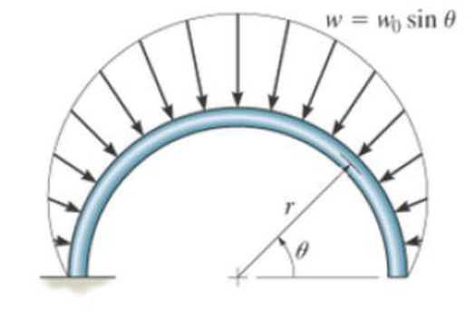
Probs. 7–39/40
Expert Solution & Answer
Want to see the full answer?
Check out a sample textbook solution
Students have asked these similar questions
Using AutoCAD
340 lb
340 lb
Δ
4. In a table of vector differential operators, look up the expressions for V x V in a cylindrical coordinate
system.
(a) Compute the vorticity for the flow in a round tube where the velocity profile is
= vo [1-(³]
V₂ = Vo
(b) Compute the vorticity for an ideal vortex where the velocity is
Ve=
r
where constant.
2πг
(c) Compute the vorticity in the vortex flow given by
Ve=
r
2лг
1- exp
(
r²
4vt
(d) Sketch all the velocity and vorticity profiles.
Chapter 7 Solutions
Engineering Mechanics: Statics & Dynamics (14th Edition)
Ch. 7.1 - In each case, calculate the reaction at A and then...Ch. 7.1 - Determine the normal force, shear force, and...Ch. 7.1 - Determine the normal force, shear force, and...Ch. 7.1 - Determine the normal force, shear force, and...Ch. 7.1 - Determine the normal force, shear force, and...Ch. 7.1 - Determine the normal force, shear force, and...Ch. 7.1 - Determine the normal force, shear force, and...Ch. 7.1 - Determine the shear force and moment at points C...Ch. 7.1 - Determine the internal normal force and shear...Ch. 7.1 - Two beams are attached to the column such that...
Ch. 7.1 - The beam weighs 280 lb/ft. Determine the internal...Ch. 7.1 - The pliers are used to grip the tube at B. If a...Ch. 7.1 - Determine the distance a as a fraction of the...Ch. 7.1 - Determine the internal shear force and moment...Ch. 7.1 - Determine the internal shear force and moment...Ch. 7.1 - Determine the normal force, shear force, and...Ch. 7.1 - The cable will fail when subjected to a tension of...Ch. 7.1 - Determine the internal normal force, shear force,...Ch. 7.1 - Determine the distance a between the bearings in...Ch. 7.1 - Determine the internal normal force, shear force,...Ch. 7.1 - The shaft is supported by a journal bearing at A...Ch. 7.1 - Determine the internal normal force, shear force,...Ch. 7.1 - Determine the internal normal force, shear force,...Ch. 7.1 - The cantilevered rack is used to support each end...Ch. 7.1 - Determine the internal normal force, shear force,...Ch. 7.1 - Determine the internal normal force, shear force,...Ch. 7.1 - Rod AB is fixed to a smooth collar D, which slides...Ch. 7.1 - Determine the internal normal force, shear force,...Ch. 7.1 - Determine the internal normal force, shear force,...Ch. 7.1 - Determine the internal normal force, shear force,...Ch. 7.1 - Determine the ratio of a/b for which the shear...Ch. 7.1 - Determine the normal force, shear force, and...Ch. 7.1 - Determine the internal normal force, shear force,...Ch. 7.1 - Determine the internal normal force, shear force,...Ch. 7.1 - Determine the internal normal force, shear force,...Ch. 7.1 - Determine the normal force, shear force, and...Ch. 7.1 - Determine the normal force, shear force, and...Ch. 7.1 - Determine the internal normal force, shear force,...Ch. 7.1 - Determine the internal normal force, shear force,...Ch. 7.1 - Determine the internal normal force, shear force,...Ch. 7.1 - Determine the internal normal force, shear force,...Ch. 7.1 - The strongback or lifting beam is used for...Ch. 7.1 - Determine the internal normal force, shear force,...Ch. 7.1 - Determine the internal normal force, shear force,...Ch. 7.1 - Determine the internal normal force, shear force,...Ch. 7.1 - The distributed loading W = W0 sin , measured per...Ch. 7.1 - Solve Prob. 7-39 for = 120. Probs. 739/40Ch. 7.1 - Determine the x, y. z components of force and...Ch. 7.1 - Determine the x, y, z components of force and...Ch. 7.1 - Determine the x, y, z components of internal...Ch. 7.1 - Determine the x, y. z components of internal...Ch. 7.2 - Determine the shear and moment as a function of x,...Ch. 7.2 - Determine the shear and moment as a function of x,...Ch. 7.2 - Determine the shear and moment as a function of x,...Ch. 7.2 - Determine the shear and moment as a function of x,...Ch. 7.2 - Determine the shear and moment as a function of x,...Ch. 7.2 - Determine the shear and moment as a function of x,...Ch. 7.2 - Draw the shear and moment diagrams for the shaft...Ch. 7.2 - Draw the shear and moment diagrams for the beam...Ch. 7.2 - Draw the shear and moment diagrams for the beam...Ch. 7.2 - Draw the shear and moment diagrams for the...Ch. 7.2 - Draw the shear and moment diagrams of the beam (a)...Ch. 7.2 - If L = 9 m, the beam will fail when the maximum...Ch. 7.2 - Draw the shear and moment diagrams for the beam....Ch. 7.2 - Draw the shear and moment diagrams for the beam....Ch. 7.2 - Draw the shear and bending-moment diagrams for the...Ch. 7.2 - The shaft is supported by a smooth thrust bearing...Ch. 7.2 - Draw the shear and moment diagrams for the beam....Ch. 7.2 - Draw the shear and moment diagrams for the beam....Ch. 7.2 - Draw the shear and moment diagrams for the...Ch. 7.2 - Draw the shear and bending-moment diagrams for...Ch. 7.2 - Draw the shear and moment diagrams for the beam....Ch. 7.2 - The shaft is supported by a smooth thrust bearing...Ch. 7.2 - Draw the shear and moment diagrams for the beam....Ch. 7.2 - The beam will fail when the maximum internal...Ch. 7.2 - Prob. 63PCh. 7.2 - Prob. 64PCh. 7.2 - Prob. 65PCh. 7.2 - Draw the shear and moment diagrams for the beam....Ch. 7.2 - Determine the internal normal force, shear force,...Ch. 7.2 - The quarter circular rod lies in the horizontal...Ch. 7.2 - Express the internal shear and moment components...Ch. 7.3 - Draw the shear and moment diagrams for the beam....Ch. 7.3 - Draw the shear and moment diagrams for the beam....Ch. 7.3 - Draw the shear and moment diagrams for the beam....Ch. 7.3 - Draw the shear and moment diagrams for the beam....Ch. 7.3 - Draw the shear and moment diagrams for the beam....Ch. 7.3 - Draw the shear and moment diagrams for the beam....Ch. 7.3 - Draw the shear and moment diagrams for the beam....Ch. 7.3 - Draw the shear and moment diagrams for the beam....Ch. 7.3 - Draw the shear and moment diagrams for the beam....Ch. 7.3 - Draw the shear and moment diagrams for the...Ch. 7.3 - Draw the shear and moment diagrams for the beam....Ch. 7.3 - Draw the shear and moment diagrams for the beam....Ch. 7.3 - Draw the shear and moment diagrams for the beam....Ch. 7.3 - Draw the shear and moment diagrams for the beam....Ch. 7.3 - Draw the shear and moment diagrams for the beam....Ch. 7.3 - Draw the shear and moment diagrams for the shaft....Ch. 7.3 - Draw the shear and moment diagrams for the beam....Ch. 7.3 - The beam consists of three segments pin connected...Ch. 7.3 - Draw the shear and moment diagrams for the beam....Ch. 7.3 - Draw the shear and moment diagrams for the beam....Ch. 7.3 - Draw the shear and moment diagrams for the beam....Ch. 7.3 - Draw the shear and moment diagrams for the beam....Ch. 7.3 - Draw the shear and moment diagrams for the beam....Ch. 7.3 - Draw the shear and moment diagrams for the beam....Ch. 7.3 - Draw the shear and moment diagrams for the beam....Ch. 7.3 - Draw the shear and moment diagrams for the beam....Ch. 7.3 - Draw the shear and moment diagrams for the beam....Ch. 7.3 - Draw the shear and moment diagrams for the beam....Ch. 7.3 - Draw the shear and moment diagrams for the beam....Ch. 7.3 - Draw the shear and moment diagrams for the beam....Ch. 7.4 - The cable supports the three loads shown....Ch. 7.4 - Prob. 95PCh. 7.4 - Determine the tension in each segment of the cable...Ch. 7.4 - Prob. 97PCh. 7.4 - The cable supports the loading shown. Determine...Ch. 7.4 - The cable supports the three loads shown....Ch. 7.4 - The cable supports the three loads shown....Ch. 7.4 - Determine the force P needed to hold the cable in...Ch. 7.4 - Determine the maximum uniform loading w, measured...Ch. 7.4 - The cable is subjected to a uniform loading of w =...Ch. 7.4 - The cable AB is subjected to a uniform loading of...Ch. 7.4 - If x = 2 ft and the crate weighs 300 lb, which...Ch. 7.4 - If yB = 1.5 ft. determine the largest weight of...Ch. 7.4 - The cable supports a girder which weighs 850...Ch. 7.4 - The cable is subjected to a uniform loading of w =...Ch. 7.4 - If the pipe has a mass per unit length of 1500...Ch. 7.4 - Prob. 110PCh. 7.4 - Prob. 111PCh. 7.4 - The cable will break when the maximum tension...Ch. 7.4 - Prob. 113PCh. 7.4 - The power transmission cable weighs 10 lb/fl. If...Ch. 7.4 - Prob. 115PCh. 7.4 - Prob. 116PCh. 7.4 - Prob. 117PCh. 7.4 - Prob. 118PCh. 7.4 - Show that the deflection curve of the cable...Ch. 7.4 - Prob. 120PCh. 7.4 - Prob. 121PCh. 7.4 - Prob. 122PCh. 7.4 - A cable has a weight of 5 lb/ft. If it can span...Ch. 7.4 - The 10 kg/m cable is suspended between the...Ch. 7.4 - Determine the internal normal force, shear force,...Ch. 7.4 - Prob. 2RPCh. 7.4 - Prob. 3RPCh. 7.4 - Prob. 4RPCh. 7.4 - Draw the shear and moment diagrams for the beam....Ch. 7.4 - A chain is suspended between points at the same...
Knowledge Booster


Learn more about
Need a deep-dive on the concept behind this application? Look no further. Learn more about this topic, mechanical-engineering and related others by exploring similar questions and additional content below.Similar questions
- In the figure, Neglects the heat loss and kinetic and potential energy changes, calculate the work produced by the turbine in kJ T = ??? Steam at P=3 MPa, T = 280°C Turbine Rigid tank V = 1000 m³ Turbine Rigid tank V = 100 m³ V = 1000 m³ V = 100 m³ The valve is opened. Initially: evacuated (empty) tank O a. 802.8 Initially: Closed valve O b. 572 O c. 159.93 Od. 415 e. 627.76 equilibriumarrow_forwardPlease find the torsional yield strength, the yield strength, the spring index, and the mean diameter. Use: E = 28.6 Mpsi, G = 11.5 Mpsi, A = 140 kpsi·in, m = 0.190, and relative cost= 1.arrow_forwardA viscoelastic column is made of a material with a creep compliance of D(t)= 0.75+0.5log10t+0.18(log10t)^2 GPA^-1 for t in s. If a constant compressive stress of σ0 = –100 MPa is applied at t = 0, how long will it take (= t1/2) for the height of the column to decrease to ½ its original value? Note: You will obtain multiple answers for this problem! One makes sense physically and one does not.arrow_forward
- A group of 23 power transistors, dissipating 2 W each, are to be cooled by attaching them to a black-anodized square aluminum plate and mounting the plate on the wall of a room at 30°C. The emissivity of the transistor and the plate surfaces is 0.9. Assuming the heat transfer from the back side of the plate to be negligible and the temperature of the surrounding surfaces to be the same as the air temperature of the room, determine the length of the square plate if the average surface temperature of the plate is not to exceed 50°C. Start the iteration process with an initial guess of the size of the plate as 43 cm. The properties of air at 1 atm and the film temperature of (Ts + T)/2 = (50 + 30)/2 = 40°C are k = 0.02662 W/m·°C, ν = 1.702 × 10⁻⁵ m2 /s, Pr = 0.7255, and β = 0.003195 K–1. Multiple Choice 0.473 m 0.284 m 0.513 m 0.671 marrow_forwardA 40-cm-diameter, 127-cm-high cylindrical hot water tank is located in the bathroom of a house maintained at 20°C. The surface temperature of the tank is measured to be 44°C and its emissivity is 0.4. Taking the surrounding surface temperature to be also 20°C, determine the rate of heat loss from all surfaces of the tank by natural convection and radiation. The properties of air at 32°C are k=0.02603 W/m-K, v=1.627 x 10⁻⁵ m²/s, Pr = 0.7276, and ẞ = 0.003279 K-1 The rate of heat loss from all surfaces of the tank by natural convection is The rate of heat loss from all surfaces of the tank by radiation is W. W.arrow_forwardA 2.5-m-long thin vertical plate is subjected to uniform heat flux on one side, while the other side is exposed to cool air at 5°C. The plate surface has an emissivity of 0.73, and its midpoint temperature is 55°C. Determine the heat flux subjected on the plate surface. Uniform heat flux -Plate, € = 0.73 Cool air 5°C 7 TSUIT Given: The properties of water at Tf,c= 30°C. k=0.02588 W/m.K, v=1.608 x 10⁻⁵ m²/s Pr = 0.7282 The heat flux subjected on the plate surface is W/m²arrow_forward
- Hot water is flowing at an average velocity of 5.82 ft/s through a cast iron pipe (k=30 Btu/h-ft-°F) whose inner and outer diameters are 1.0 in and 1.2 in, respectively. The pipe passes through a 50-ft-long section of a basement whose temperature is 60°F. The emissivity of the outer surface of the pipe is 0.5, and the walls of the basement are also at about 60°F. If the inlet temperature of the water is 150°F and the heat transfer coefficient on the inner surface of the pipe is 30 Btu/h-ft².°F, determine the temperature drop of water as it passes through the basement. Evaluate air properties at a film temperature of 105°C and 1 atm pressure. The properties of air at 1 atm and the film temperature of (Ts+ T∞)/2 = (150+60)/2 = 105°F are k=0.01541 Btu/h-ft-°F. v=0.1838 × 10⁻³ ft2/s, Pr = 0.7253, and ẞ = 0.00177R-1arrow_forwardhand-written solutions only, please. correct answers upvoted!arrow_forwardhand-written solutions only, please. correct answers upvoted!arrow_forward
- ! Required information Consider a flat-plate solar collector placed horizontally on the flat roof of a house. The collector is 1.3 m wide and 2.8 m long, and the average temperature of the exposed surface of the collector is 42°C. The properties of air at 1 atm and the film temperature are k=0.02551 W/m-°C, v = 1.562 × 10⁻⁵ m²/s, Pr = 0.7286, and ẞ= 0.003356 K-1 Determine the rate of heat loss from the collector by natural convection during a calm day when the ambient air temperature is 8°C. The rate of heat loss from the collector by natural convection is W.arrow_forwardhand-written solutions only, please. correct answers upvoted!arrow_forwardhand-written solutions only, please. correct answers upvoted!arrow_forward
arrow_back_ios
SEE MORE QUESTIONS
arrow_forward_ios
Recommended textbooks for you
 International Edition---engineering Mechanics: St...Mechanical EngineeringISBN:9781305501607Author:Andrew Pytel And Jaan KiusalaasPublisher:CENGAGE L
International Edition---engineering Mechanics: St...
Mechanical Engineering
ISBN:9781305501607
Author:Andrew Pytel And Jaan Kiusalaas
Publisher:CENGAGE L
Solids: Lesson 53 - Slope and Deflection of Beams Intro; Author: Jeff Hanson;https://www.youtube.com/watch?v=I7lTq68JRmY;License: Standard YouTube License, CC-BY